background image

Cod. 7.020.0903 - Rev

. 07/1

1

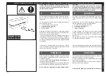
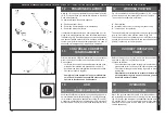
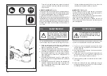
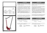
-  Tirare la leva di posizionamento manubrio di comando 

(pos.1) e riportare il manubrio nella posizione di riposo 

(fig.12/1pos.A).

ARRESTO IMMEDIATO

 (fig.14/2)

In caso di normale utilizzo per eseguire l’arresto del coman-

do di salita o discea azionato è sufficiente rilasciare la leva 

di comando salita/discesa cilindro di sollevamento (pos.3) 

e quest’ultima rientrerà in posizione centrale 

A

.

Rilasciando la leva di consenso al funzionamento (pos.2) si 

ha analogamente l’arresto di qualsiasi azionamento del sol-

levatore in quanto si interrompe l’alimentazione pneumatica.

Eseguendo qualsiasi delle operazioni descritte il sollevatore 

mantiene comunque il carico sollevato nella posizione in 

cui si trova.

15/1

15

MANUTENZIONE

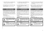
Ogni operazione di manutenzione 

deve essere effettuata  con il gruppo 

cilindro di sollevamento completa-

mente chiuso e l’alimentazione pneu-

matica scollegata.

Per il perfetto funzionamento e una maggiore durata del Vo-

stro sollevatore seguire attentamente le seguenti istruzioni:

1

 - Pulire accuratamente la macchina ed in particolare il 

cilindro del sollevatore da eventuali residui di polvere, 

grasso  o da altri elementi esterni.

2

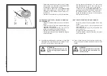
 - Lubrificare periodicamente le viti di snodo del manico ed 

il perno di movimentazione del manubrio di comando.

3

 - Controllare  periodicamente  il  livello  d’olio  nel  gruppo 

filtro-regolatore-lubrificatore, ed eventualmente ripristi-

narlo consultando il manuale d’uso e manutenzione di 

detto dispositivo.

4

 - Controllare periodicamente che non vi siano ammac-

cature o fuoriuscite d’olio dagli sfilamenti del cilindro di 

sollevamento.

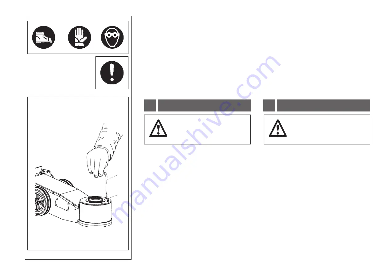
5

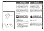
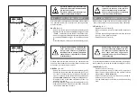
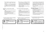
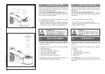
 - Controllare periodicamente il livello d’olio nel serbatoio 

mediante l’apposita asta posta sotto il tappo (fig.15/1 

pos.3) del serbatoio stesso operando secondo le se-

guenti modalità (fig.15/1):

15

MAINTENANCE

32

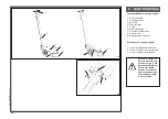
-  Pull the handlebar positioning lever (1) and return the 

handlebar to the stowed position (A fig.12/1).

IMMEDIATE STOP (fig.14/2)

During normal operation, to stop upward or downward 

movement simply release the lifting cylinder up/down lever 

(3); it will return to the central position 

A.

Releasing the on-off lever (2) also stops all jack movements, 

since it cuts off the compressed air supply.

When either of these procedures is followed, the jack will 

still hold the raised load in the position reached when the 

stop was triggered.

All servicing work must be carried out 

with the lifting cylinder unit fully re-

tracted and the compressed air supply 

disconnected.

To ensure that this jack works perfectly over the years, carry 

out the routine maintenance schedule described below:

1 - Clean the machine thoroughly, particularly the lifting 

cylinder, removing any residues of dust, grease or other 

external materials.

2 - Lubricate the handle articulation screws and handlebar 

hinge pin periodically.

3 - Check the oil level in the filter-regulator-lubricator unit 

periodically and top up if necessary, referring to the 

device’s own use and maintenance manual.

4 - Check the lifting cylinder rod extension points for dents 

or oil leaks.

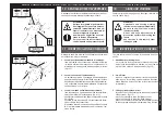
5 - Check the oil level in the tank periodically using the 

dipstick underneath the cap (3 fig.15/1) of the tank itself, 

proceeding as follows (fig.15/1):

3

2

Содержание SCM 230

Страница 1: ...uch und wartung Manual de uso y mantenimiento Sollevatori Oleopneumatici Air Hydraulic Jacks Cric Hydropneumatiques Hydropneumatische Wagenheber Elevadores Oleoneum ticos CORMACH S R L CORREGGIO MACCH...

Страница 2: ......

Страница 3: ...nnten Es entspricht der Maschinenrichtlinie 2006 42 CE und nachfolgender nderun gen sowie der Europ ischen Norm EN 1494 vom November 2000 entsprechen DECLARACI N DE CONFORMIDAD seg n la Directiva 2006...

Страница 4: ...Cod 7 020 0903 Rev 07 11 4...

Страница 5: ...ouvement Gefahrt Bew egliche mechanische Organe Peligro Partes mecanicas en movimlento Pericolo di schiacciamento Crushing danger Risque d ecrasement Gefahrt Quetschgefahr Peligros de aplastamiento Ob...

Страница 6: ...des Produktes Die Anleitung in einem bekannten und leicht zug nglichen Ort aufbewahren und bei Bedarf zu Rate ziehen Alle Bediener des Produktes m ssen zwecks Einsichtnahme Zugang zur Anleitung haben...

Страница 7: ...MMANDES 12 POSITION DE TRAVAIL 13 CONTROLE DU BON FONCTIONN 14 UTILISATION 14 1 UTILISATION DU CRIC 14 2 MONTEE DESCENTE ARRET 15 ENTRETIEN 16 INCONV CAUSES REMEDES 17 REMISAGE 18 MISE A DECHARGE 19 G...

Страница 8: ...damental rules and criteria to be adopted when using and maintaining the jack Air hydraulic jacks are constructed to partially lift vehicles for the sole purpose of removing replacing wheels Any other...

Страница 9: ...Wagenhebers wurde bez glich der Zeit der Best ndigkeit bis zur Erm dung mechanisch strukturelle Erm dung eine Betriebslebensdauer von 10 zehn Jahren mit ca 200 000 zweihunderttausend Hubzyklen verans...

Страница 10: ...een Standard supply colour Frame Cylinder LpA 73 4 dB A Acoustic pressure level at operator position UP LpA 67 6 dB A Acoustic pressure level at operator position DOWN N sfilate pistone di sollevament...

Страница 11: ...ck BAR P S I 500 Lt min Luftverbrauch 1 4 Gas Druckluftanschlu Innengewinde Rot Gr n Standardfarbe Rahmen Zylinder LpA 73 4 dB A Schalldruckpegel am Arbeitsplatz w hrend ANHEBUNG LpA 67 6 dB A Schalld...

Страница 12: ...la comando discesa Valvola controllo discesa Valvola di massima olio Pompa pneumoidraulica Serbatoio olio Valvola di depressione Valvola di comando salita discesa Asta livello olio Valvola di massima...

Страница 13: ...c 1 4 GAS femelle ABMESSUNGEN 3 2 HYDROPNEUMATISCHE SCHEMA 3 3 DIMENSIONES 3 2 Dimensiones elevadores fig 3 1 ESQUEMA OLEONEUMATICO 3 3 1 2 3 4 5 6 7 Leyenda esquema oleoneum tico fig 3 2 8 9 10 11 12...

Страница 14: ...tamente proibito effettuare qualsiasi tipo di operazione al di sotto del veicolo sollevato per mezzo del sollevatore oleopneumatico Lavorando alle ruote del veicolo sollevare lo stretto neces sario af...

Страница 15: ...en es sollte nach M glichkeit unbeladen sein Eine eventuelle Ladung mu stabil sein Es ist verboten mehrere Wagenheber zum gleichzei tigen Ein oder Ausbau mehrerer Fahrzeugr der zu benutzen Es ist verb...

Страница 16: ...flessibili e 6 mm fig 5 2 pos 8 9 Collegamenti idraulici l alimentazione idraulica fra generatore di pressione e cilindro garantita mediante particolari condotti interni ai corpi di tali elementi e da...

Страница 17: ...er Last abb 5 2 pos 3 4 Absenk Kontrollventil sorgt f r eine kontrollierte Absenkgeschwindigkeit abb 5 2 pos 4 5 Absenk Steuerventil Bremsmechanismus mit dem die Absenkung der Last kontrolliert und ge...

Страница 18: ...in order to reduce shipping dimen sions Depending on the customer s requirements the machine may be supplied packed in four different ways 1 In triple wall cardboard with pallet 2 In wooden crate with...

Страница 19: ...ine sichtbaren Sch den aufweist Bei Sch den oder im Zweifelsfall die Vorrichtung nicht benutzen sondern den H ndler informieren Die Packteile d rfen nicht f r Kinder zug nglich aufbewahrt werden weil...

Страница 20: ...ortunamente fissate all interno della cerniera impediscono al manubrio un pos sibile ribaltamento verso il telaio del sollevatore durante le operazioni di normale utilizzo 20 Choose the place the mach...

Страница 21: ...u allen Personen die nicht be sonders geschult sind und keine Ge nehmigung haben verboten werden diesen Bereich zu betreten Die Umgebungsbedingungen m ssen den folgenden Richtwerten entsprechen Relati...

Страница 22: ...aria Regolatore di pressione Manometro aria Lubrificatore a nebbia d olio Vite di regolazione lubrificazione Vite di scarico condensa 22 1 Before making any connections check that the system pressure...

Страница 23: ...f r den Verbrauch der Maschine ausreichend ist 500 l Min Jeder Schaden der sich aus der Nichtbeachtung dieser Anweisungen ergibt enthebt den Hersteller von jeder Haftung und f hrt zum Verfall des Gar...

Страница 24: ...mento 8 Serbatoio olio 9 Gruppo pompa e piastra Descrizione dei comandi fig 9 2 1 Leva di posizionamento manubrio 2 Leva di consenso al funzionamento 3 Leva di comando salita discesa Durante le operaz...

Страница 25: ...corps le plus loin possible des parties en mouvement Les colliers bracelets v tements flottants peuvent constituer un danger pour l op ra teur Hauptkomponenten des Wagenhebers abb 9 1 1 Fahrgestell 2...

Страница 26: ...tare la leva in posizione C per comandare la disce sa del cilindro di sollevamento Riportando la leva di comando nella posizione centrale A si ha l immediata disattivazione del comando fun zione di st...

Страница 27: ...der somit in unterschiedliche Arbeitspo sitionen gebracht werden kann abb 12 1 2 Betriebs Freigabehebel Bei dessen Bet tigung erfolgt die F rderung der Druc kluft zum Steuerventil das die Funktionen d...

Страница 28: ...evatore nel punto esatto vedi indicazioni dal manuale del veicolo in cui si intende sollevare il veicolo 14 OPERATION USING THE JACK 14 1 28 A B C Fig 12 1 shows the various working positions A B C wh...

Страница 29: ...rauch des Wagenhebers sind einige Kontrollen zur Gew hrleistung der Funktionst chtigkeit erforderlich Notwendige Vorkontrollen Korrekte und funktionelle Druckluftversorgung des Wagenhebers sowie Betri...

Страница 30: ...re la leva nella suddetta posizione fino alla completa chiusura del cilindro di sollevamento Riportare la leva di comando salita discesa pos 3 in posizione centrale A Rilasciare la leva di consenso al...

Страница 31: ...hebung sicherstellen da keine Fremdk rper zwischen die einzelnen Ausziehelemente und die Abstreiferdichtungen gelangen da dies zu irreparablen Sch den an der Hubzylindereinheit f hren w rde Ist der Ko...

Страница 32: ...periodicamente che non vi siano ammac cature o fuoriuscite d olio dagli sfilamenti del cilindro di sollevamento 5 Controllare periodicamente il livello d olio nel serbatoio mediante l apposita asta p...

Страница 33: ...d die Druc kluft versorgung unterbrochen wurde F r den einwandfreien Betrieb und eine l ngere Haltbarkeit Ihrer Wagenheber sind die folgenden Anweisungen genau zu beachten 1 Maschine und insbesondere...

Страница 34: ...vertenza di peri colo e dei carichi massimi di sollevamento ATTENZIONE Trattare i lubrificanti esausti in con formit alle leggi vigenti antinquina mento 34 15 2 4 5 Use the spanner provided pos 2 to u...

Страница 35: ...getellers ausdrehen und diesen nach au en drehen Die Schraube ohne Kopf abb 15 2 pos 5 lockern und die Hubsteuerung bis zum Austritt von l bet ti gen Die Schraube ohne Kopf wieder eindrehen abb 15 2 p...

Страница 36: ...elow the minimum 1 Top up the fluid level inside the hydraulic sy stem tank see instructions in point 15 Excessive hydraulic fluid is seen to leak throu gh the hole on the pump unit aeration filter se...

Страница 37: ...efect a la carrera de subida de modo incompleto 1 El nivel del aceite en el interior del dep sito hidr ulico es inferior al nivel m nimo 1 Restablecer el nivel del aceite en el dep sito hidr ulico v...

Страница 38: ...ot work properly do not use it and call for technical assistance 17 ACCANTONAMENTO 17 STORING In caso di inattivit del sollevatore per un lungo periodo 3 4 mesi provvedere ad effettuare le seguenti op...

Страница 39: ...a r cnica PROBLEMAS CAUSAS REMEDIOS Le groupe pompe fonctionne parfaitement mais le v rin de lev e ne parvient pas effec tuer la mont e sous charge 1 Il y a certainement des impuret s dans les vannes...

Страница 40: ...cially metal and plastic parts When scrapping the jack the regulations in force require the user to take special care with regard to particularly pollutant materials present on the machine such as Pla...

Страница 41: ...s piezas deben ser desmontadas y separadas en funci n de su posible recuperaci n en particular el material ferroso y el material pl stico En el momento de efectuar el desguace el usuario ac tuando sie...

Страница 42: ...s of any components in which actual construction defects have been identified The Manufacturer declines all responsibility and the warranty becomes null and void if the machine has been tampered with...

Страница 43: ...stets re gelm ig auf ihre Unversehrtheit und Funktionst chtigkeit zu kontrollieren Los elevadores oleoneum ticos est n garantizados por 24 venteiquatros meses a contar del d a de la entrega respecto...

Страница 44: ...lo standard consentito inserire un elemento di spessore se previsto fig 20 1 Non consentito utilizzare spessori di tipo diversi Nel caso in cui siano utilizzati spessori diversi da quelli forniti dal...

Страница 45: ...utilise des cales autres que celles fournies par le fabricant celui ci ne sera pas responsable des endom magements provoqu s par leur utilisation Pour l application de la cale fournie proc der comme...

Страница 46: ...055 0006 3 094 0218 2 025 0010 3 094 0013 3 072 0104 3 072 0004 3 093 0013 6 075 0020 3 094 0217 3 070 0003 3 070 0057 5 085 0008 Q TA 1 1 1 2 2 1 1 1 1 1 2 2 2 2 2 2 2 1 6 2 2 2 4 2 2 1 4 3 1 1 1 1 1...

Страница 47: ...0006 3 031 0049 3 094 0006 6 075 0008 3 021 0002 6 066 0043 5 064 0036 3 079 0001 3 094 0211 3 072 0106 3 072 0006 3 072 0008 3 031 0054 5 013 0011 3 094 0217 3 093 0010 3 094 0213 3 031 0008 3 072 0...

Страница 48: ...0012 5 064 0023 3 052 0004 5 094 0308 3 094 0014 3 094 0203 3 072 0103 3 076 0013 5 046 0008 5 064 0031 5 066 0013 3 051 0064 5 094 0304 3 094 0216 3 031 0016 3 070 0061 5 094 0311 5 065 0010 3 053 0...

Страница 49: ...OU raccord busette soupape garniture piston ressort pivot o ring tete KODE 3 070 0058 3 070 0059 3 052 0003 3 076 0012 5 084 0001 3 053 0101 5 068 0067 5 086 0003 3 094 0008 3 094 0009 3 051 0072 5 05...

Страница 50: ...3 051 0040 5 034 0076 7 078 0054 3 094 0033 5 018 0734 7 078 0122 3 054 0410 3 054 0409 Q TA 1 1 2 2 4 1 1 1 1 1 1 4 1 1 DESCRIZIONE o ring sede valvola o ring anello antiestrusore vite guida sfera mo...

Страница 51: ...guide de bille ressort guide de bille o ring plaque connection soupape vis chemise kit soupape de maxi air kit joints plaque kit joints pompe KODE 3 051 0107 5 028 0039 3 051 0108 3 005 0001 3 094 00...

Страница 52: ...51 0177 3 051 0178 3 053 0110 3 051 0176 5 013 0047 3 051 0077 3 051 0140 6 069 0215 5 027 0008 7 078 0114 7 078 0121 3 054 0421 Q TA 1 1 1 1 1 1 1 1 1 1 1 1 3 1 1 1 1 1 1 1 2 1 1 1 1 DESCRIZIONE BASA...

Страница 53: ...d etancheite o ring segment anneau d etancheite tube telescopique o ring o ring niveau d huile couvercle soupape soupape kit joints KODE 5 012 0003 5 090 0020 6 090 0012 5 013 0046 3 052 0003 5 006 0...

Страница 54: ...Cod 7 020 0903 Rev 07 11 54...

Страница 55: ......

Страница 56: ...Rev 0 07 2011 CORMACH S R L CORREGGIO MACCHINE Via M Pignedoli 2 42015 CORREGGIO RE ITALY Tel 39 0522 631274 Fax 39 0522 631284 E mail cormach cormachsrl com www cormachsrl com...

Отзывы: