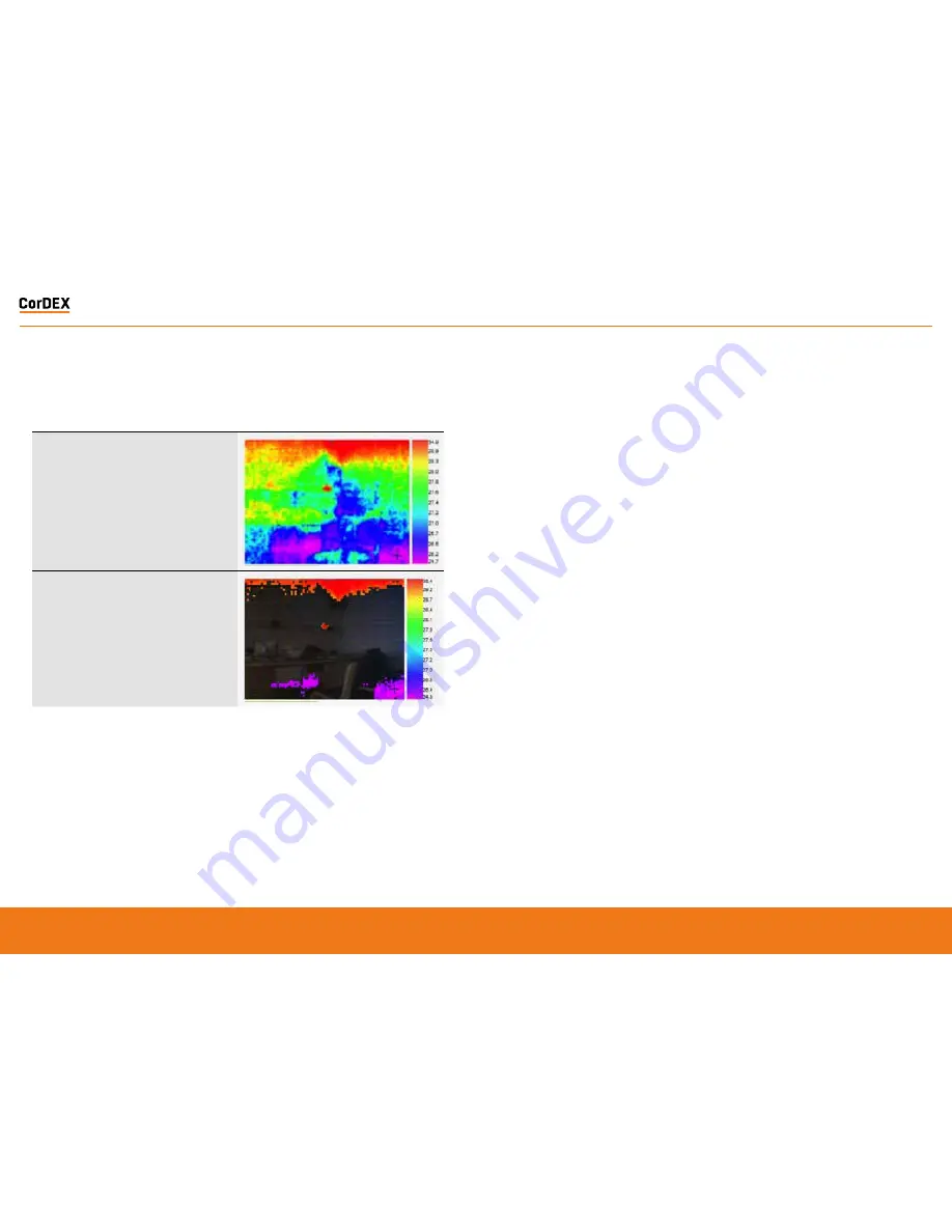
Thermal only
The thermal image captured by the 80x60 infrared
camera. Due to the resolution of the infrared camera
alone, this mode is not recommended for scenes with a
low dynamic temperature range.
Isotherm overlay
When a rising and/or falling isotherm is configured and
Isotherm overlay selected, the areas which fall into
the Isotherm alarm condition are coloured and shown
on the image. This example has both rising and falling
isotherms configured. The rising isotherm is shown in
red/orange, the falling isotherm is show in purple.
To select an Image Type, click the drop down
box and select the desired option, then click
the Send to Camera button. The command will
be transmitted to the camera and the image
refreshed after a few moments with your new
settings applied.
Setting Rising/Falling Isotherms
An Isotherm is an alarm condition where a
temperature level which is above (rising) or
below (falling) the Isotherm setpoint causes
the image in that set location to be highlighted
on the visual image by means of a colour.
To Set a Rising Isotherm, click the OFF/ON
toggle switch to the ON position (green) and
insert the alarm value in the box adjacent to
the button.
Click “Send to Camera”.
Any temperature in the cameras Field of View
(FOV) above this temperature will be coloured.
To Set a Falling Isotherm, click the OFF/ON
toggle switch to the ON position (green) and
insert the alarm value in the box adjacent to
the button.
Click “Send to Camera”.
Any temperature in the cameras Field of View
(FOV) below this temperature will be coloured.
It is possible to set both Rising and
Falling Isotherms on the same camera
simultaneously.
Toggling the onboard LED illuminator
The camera is equipped with an onboard LED
illuminator for extremely low light situations.
To toggle the LED illuminator, click the LED
OFF/ON button and then click the Send to
Camera button.
Spot temperatures
The camera has three spot temperature
points; Hot, Cold and Dynamic.
The Hot temperature identifier puts a red
cross on the hottest part of the image.
The Cold temperature identifier puts a blue
cross on the coldest part of the image.
The Dynamic temperature measurement
shows the temperature of the cursor in the
Spot Temperature box.
MODBUS Registers & Coordinates
When Configuring Programmable Logic
Controllers (PLCs) to perform actions based
upon MN4xxx measurements, it is necessary
to be able to define either the MODBUS
Register of a particular point in the image
and/or its x,y coordinates.
To do this, hover the mouse over the point
on the image you are interested in and the
MODBUS Reg will be shown in the Modbus
Reg field, in brackets, the x,y coordinates for
the same MODBUS Register are shown.
RUGGED
AUTHORITY
MONITIR Series Thermal Imaging Cameras
– User Manual
19
Document Reference MONITIRSERIESUM Rev. A


