


Accelnet & Stepnet Plus Panels STO Manual
16-01338 Rev 00
Page 14 of 34
Copley Controls
7.0 STO Architecture and Function
The STO function in
Accelnet & Stepnet Plus Panel
s is suitable for use in safety loops up to SIL 3 and/or
Cat. 3 PL d performance. Because Cat. 3 PL d performance requires that the safety function continues to operate
even in the event of two failures, the STO circuit concept uses a quasi three-channel architecture. This
architecture is shown in the system block diagram for a BE2 2-axis servo drive below.
In the Safe State, the drive will not produce torque or force in the motor. The STO function achieves and
maintains a safe state by disabling the ability of the attached motor(s) to produce torque/force. This halts any
drive induced acceleration already in process and prevents initiation of motion. The expectation is that an inability
of the motor to produce torque/force translates into a reduction of risk of hazardous motion for the larger system.
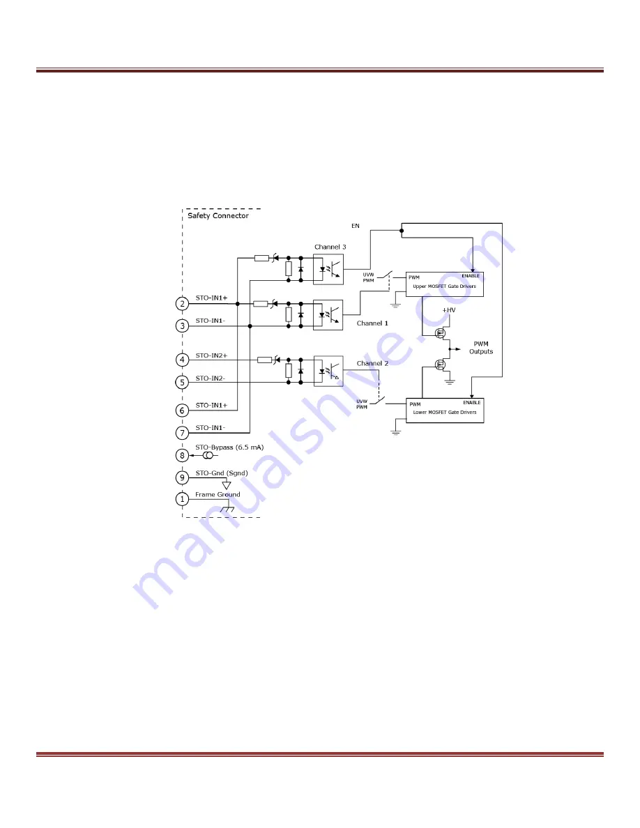
The STO circuit concept involves disabling the ability of the motor drive output stages to produce current. The
output stage consists of one subset of high side output MOSFETs that switch motor terminals to the positive rail
of the DC bus (+HV), and a second subset of low side output devices that switch motor terminals to negative rail
of the DC bus (HVCOM). The basic STO circuit architecture is derived from the fact that current flow in the motor,
and therefore torque/force production, requires both subsets to function. STO Channel 1 disables the drive (both
axes) by removing power from the high side MOSFET gate drives and STO Channel 2 disables the drive (both
axes) by removing power from the low side MOSFET gate drives.
Fig. 2


