Cooper WaveLinx Wired SC-UN Скачать руководство пользователя страница 16

2. 

Highlight the ‘Time and Date’ option and press the 

ENT


button. The current time and date settings will be displayed 

with the hour entry highlighted:

Timeclock manager

 Time and Date
 

13

:26

  2 June 2008

3. 

Use the up and down buttons to move the highlight to the 

required item. Then use the left and right buttons to alter 

the highlighted item.

4. 

Press the 

ENT

 button to save and return to the Timeclock 

manager menu screen.

Viewing Power Data Readings

The Power data section provides useful feedback and 

confirmation of the total power demanded by the controller as 

a whole, the power demand on each phase and also the power 

drawn on each channel.

To Access Power Data

1.  From the ‘Operation’ menu, select the ‘Power data’ option 

and press the 

ENT

 button. The screen will show the total 

power currently being drawn as well as two options:

Power data

  Total power  2.39kW

  Display by phase

  Display by channel

2. 

Highlight the ‘Display by phase’ option and press the 

ENT


button to view the phase power distribution:

Power data - Phase

 Phase A    1.75kW
 Phase B    1.65kW
 Phase C    0.95kW

Press the 

ESC

 button to return to the previous level.

3.  Highlight the ‘Display by channel’ option and press the 

ENT


button to view the channel power distribution:

Power data - Channels

  Channel 1: 0.101kW
  Channel 2: 0.130kW
  Channel 3:   0kW
   Channel 4: 0.500kW

Press the 

 button to view further channels and press the 

ESC

 button to return to the previous level.

Setting Communications Options

The Communications options section allows you to determine 

which control protocols should be enabled.

To Set Communications Options
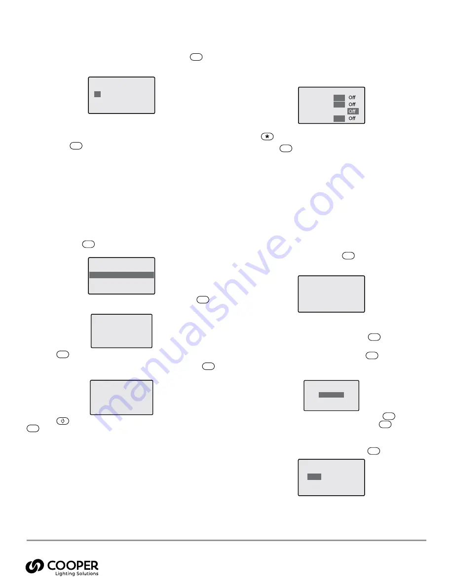
1. 

From the ‘Operation’ menu, select the ‘Communications’ 

option and press the ENT button. The screen will show the 

available control protocols and their current settings:


  v

Communications - options

  iCANnet 

On


  Ethernet 

On


  DMX 

On 

  RS485 

On


2.  Highlight the option that you wish to alter and then press 

the 

 button to change its ON/OFF status.

3.  Press the 

ENT

 button to save your changes and exit.

Changing the Operation Menu Password

The unit uses two passwords, one for the operation menu and 

another for the configuration menu. When the unit is supplied, 

there are initially no passwords. You are strongly recommended 

to set separate operation and configuration menu passwords at 

the earliest opportunity. After doing so, ensure that the relevant 

users are informed of the new passwords.

To Set/Change the Operation Menu Password

1.  From the ‘Configuration’ menu, select the ‘Password 

Manager’ option and press the 

ENT

 button. If a previous 

password has been set, the screen will prompt you to enter 

the current password:

Password manager

Enter current password

XXXX

Use the keypad to enter the current password. As you type, each 

digit will be represented by an ‘X’.
If you enter a character incorrectly, press the 

ESC

 button to 

erase it.

When you have entered the code, press the 

ENT

 button.

2.  Highlight the required password to set/change: Operation 

or Config, then press the ENT button.

Password manager

Choose password

Operation

Config

3. 

Enter your new code (4 digits) and press the 

ENT

 button. 

Then re-enter the code again and press the 

ENT

 button. 

If the two new codes match, you will be given the option to 

save.

4. 

Highlight the ‘Yes’ option and press the 

ENT

 button.

Change password?


Yes


No 

Warranties and Limitation of Liability

Please refer to 

www.cooperlighting.com 

for our terms and conditions. 

MN503104ML   

page 16

February 2021

Cooper Lighting Solutions

1121 Highway 74 South

Peachtree City, GA 30269

P: 770-486-4800

www.cooperlighting.com

For service or technical assistance:

1-800-553-3879

Canada Sales 

5925 McLaughlin Road

Mississauga, Ontario L5R 1B8

P: 905-501-3000

F: 905-501-3172

© 2021 Cooper Lighting Solutions

All Rights Reserved.


Product availability, specifications, 

and compliances are subject to 

change without notice.

Universal Source Controller

WaveLinx Wired

Содержание WaveLinx Wired SC-UN

Страница 1: ...ly by a qualified electrician The installation must comply with the appropriate electrical codes and regulations in force in your area The Universal Source Controllers are designed for indoor installa...

Страница 2: ...ibution to Circuits 10 Supply to Internal Circuitry 10 Load Wiring 10 High Voltage Load Wiring 10 Total Load Per Channel 11 Load Wire Gauges 11 Earth Connections 11 High Voltage Load Wiring Flows 11 T...

Страница 3: ...N 1P ML 20 120 VAC 1 Phase 6 Main Lugs 16A per Channel SC120 12 UN 1P ML 20 12 SC120 06 UN 3P ML 20 3 Phase 6 SC120 12 UN 3P ML 20 12 SC120 24 UN 3P ML 20 24 SC277 06 UN 1P ML 20 277 VAC 1 Phase 6 SC2...

Страница 4: ...in 517 mm 27 8 in 707 mm 0 89 in 22 5 mm 0 89 in 22 5 mm 0 98 in 25 mm 0 98 in 25 mm 4 53 in 115 mm 4 53 in 115 mm 1 1 in 28 mm 1 1 in 28 mm 1 1 in 28 mm 1 1 in 28 mm 1 1 in 28 mm 1 1 in 28 mm 13 76...

Страница 5: ...cian The installation must comply with the appropriate electrical codes and regulations in force in your area The Universal Source Controllers are designed for indoor installation and use only The uni...

Страница 6: ...the minimum distances to walls and other equipment shown in the diagrams below are maintained Also ensure that the stated ambient atmosphere requirements are not exceeded Refer to Important points fo...

Страница 7: ...sufficient strength and quality to safely hold the unit ES C 1 2 0 EN T 3 4 5 6 7 8 9 1 2 in 30 mm 1 2 in 30 mm 1 2 in 30 mm 34 8 in 885 mm 54 32 in 1379 8 mm 54 32 in 1379 8 mm 13 4 in 340 mm 13 4 in...

Страница 8: ...lace the two upper and two lower fixing screws Supply Wiring Wiring Flow The Universal Source Controller range has been designed to provide a clear layout and logical progression for all power circuit...

Страница 9: ...uit 277V 2 0 AWG 70 mm2 2 0 AWG 70 mm2 2 AWG 35 mm2 SUPPLY EARTH HOT NEUTRAL Three Phase Supply The Universal Source Controllers are available in three phase supply variants ote N Check the stated vol...

Страница 10: ...uitry The internal power supply that feeds the control panel and associated circuitry can draw its power from any and all phases so that it will still operate in the event that not all supply phases a...

Страница 11: ...uits and couplers Please see the wiring flow diagram on page 8 Typical Load Connections The examples below show some of the most typical loads and the way in which they are connected to a Source Contr...

Страница 12: ...0V 0V 0V 0V For each circuit the low voltage control protocol to be used is selected using the configuration menu on the control panel The programming of the Source Controller channels is covered with...

Страница 13: ...w the control panel accessible either through a removable mini panel or when the complete casing is removed Termination The iCAN DMX and RS 485 are daisy chain protocols that all require termination o...

Страница 14: ...tton for menu navigation Clear Text Display Link and Status Indicators Flashes Regularly to Indicate Correct System Operation When ON indicates that the timeclock function is enabled Where multiple SC...

Страница 15: ...ss the ENT button Depending on the chosen option you will be able to affect outputs as follows All Channels Use the and buttons to adjust the output level 0 to 100 for all channels When the required o...

Страница 16: ...ighlight the option that you wish to alter and then press the button to change its ON OFF status 3 Press the ENT button to save your changes and exit Changing the Operation Menu Password The unit uses...

Отзывы: