


Accessing the Operation Menu
During normal service of the Universal Source Controller, the
control panel screen shows only the time, date and device
number.
To Access the Operation Menu
1.
Press the
ENT
button to display
the Select Access Level menu.
2.
With the ‘Operation’ option
highlighted, press the
ENT
button.
3. If requested, enter the four digit
operation password and press
the
ENT
button.
ote:
N
When the unit is supplied, there
is initially no password - see the
section ‘Changing the operation
menu password’ to set one.
4. If the password is accepted, the
main ‘Operation Menu’ will be
displayed.
Menu Navigation
Within the control panel menu system, use the following
buttons to navigate:
Use the arrow buttons to move highlight bar
to the required option.
ENT
Press to enter an option or to save your changes to an
item.
ESC
Press to escape from an option to the previous level.
Operation Menu Contents
The operation menu provides the following options:
Overriding Channels
The override options allow you to alter the output levels on
channels directly from the control panel. You can choose to
alter all channels collectively, alter selected channels or request
a particular pre-programmed scene.
To Override Channels
1.
From the ‘Operation’ menu, select the ‘Channel override’
option and press the
ENT
button. The screen will show the
three options:
Override - options
All channels
Each channel
Select scene
2.
Highlight the required option and press the
ENT
button.
Depending on the chosen option you will be able to affect
outputs as follows:
All Channels
- Use the
and
buttons to adjust the
output level (0 to 100%) for all channels. When the required
output level is displayed, press the
ENT
button.
Each Channel
- Highlight the required channel number
using the
and
buttons, then press the
ENT
button.
For the chosen channel, use the
and
buttons
to adjust the output level (0 to 100%). When the required
output level is displayed, press the
ENT
button.
Select Scene
- Highlight the required scene number using
the
and
buttons, then press the
ENT
button.
Setting the Time and Date
The Timeclock manager option contains numerous features
related to the time and date, including daylight saving time,
global coordinates and the selection of changes to channel
outputs at set times. For further information about the other
Timeclock manager features, please refer to the accompanying
System Manual.
To Adjust the Time and Date
1.
From the ‘Operation’ menu, select the ‘Timeclock manager’
option and press the
ENT
button. The screen will show the
four options:
Timeclock manager
Time and Date
Events
Coordinates
DST
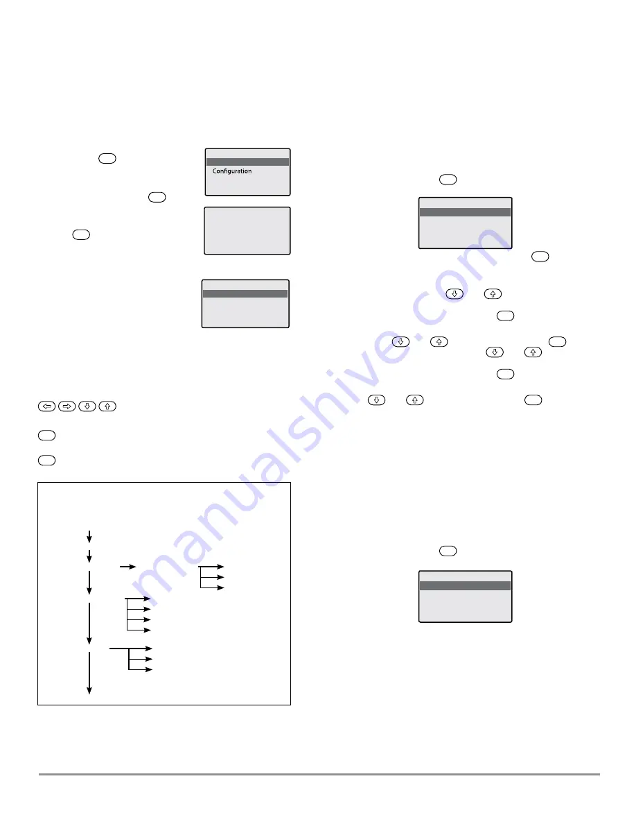
GUI help/Operation
Operation Menu
Channel Override
Override - Options
All Channels
Total Power
Time & Date
Coordinates
DST
Events
Each Channel
Display Power by Phase
Select Scene
Display Power by Channel
Timeclock Manager
Power Data
Communications
Operation Menu
GUI help/operation
Channel override
Timeclock manager
Power data
Select Access Level
Operation
Contact Cooper
Operation
Password
XXXX
Universal Source Controller
WaveLinx Wired
MN503104ML
page 15
February 2021
www.cooperlighting.com