2.
Safety Instructions
"
The device shall only be used
for its intended purpose and
in undamaged and perfect
condition!
"
Only genuine CEAG spare
parts may be used for re-
placement and repair!
"
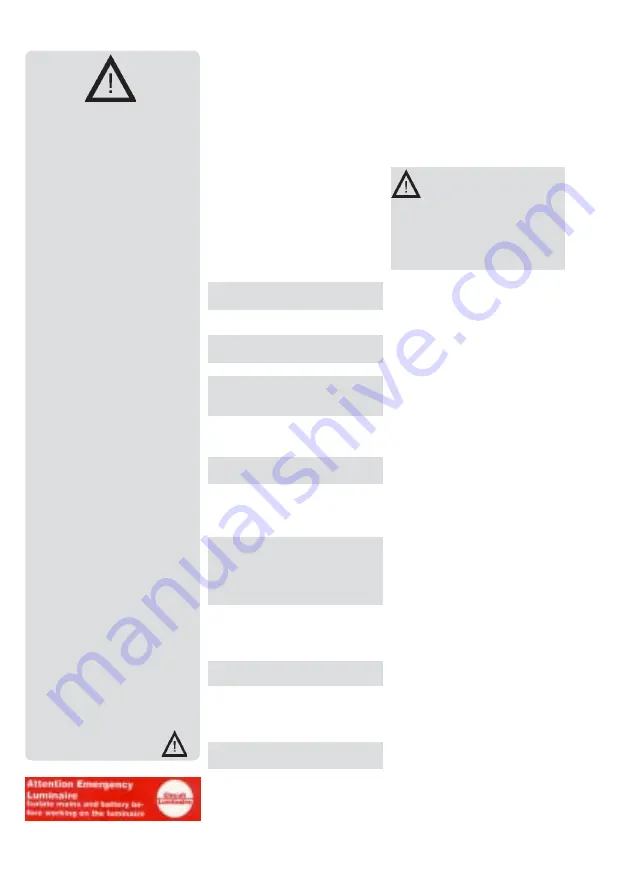
When working on the emer-
gency luminaire make sure
that it is disconnected from
the voltage! Pay attention to
the different power supplies
in mains or battery opera-
tion. Fig.14 shows the
indication label on the
emergency luminaire.
"
Prior to its initial operation,
the luminaire will have to be
checked in accordance with
the instructions as per
section Installation!
"
Carry out the marking of the
emergency luminaire: Assign
the circuit, the luminaire No.
and ID-No. and enter them.
"
The manual log book shall be
performed in compliance with
the national regulations.
"
Any foreign matter shall be
removed from the luminaire
prior to its initial operation!
"
Observe the national safety
rules and regulations for pre-
vention of accidents as well
as the safety instructions
included in these operating
instruction marked with
Fig. 14
3. Conformity with
Standards
Conform to: EN 60 598-1,
EN 60 598-2-22, EN 1838, DIN
VDE 0108/10.89.
Low-voltage directive
93/68/EEC,
EMC directive 89/336/EEC.
Note: In spite of CE conformity,
there may be a mutual
influence on equipment and
luminaires.
Developed, manufactured and
tested in accordance with DIN
EN ISO 9001.
4. Technical data
Input voltage:
230/240 V AC
50 Hz
Rated current
(AC):
70 mA
Power con-
sumption (AC): 16 VA
Lamp:
8 W/T16
Rated lumi-
nous flux of
the lamp:
450 lm
Rated lumi-
nous flux: 40% (phi
E
/phi
nominate
)
at the end of operating cycle
Insulation
class :
II
Protection
category acc.
to EN 60529 IP 41
Option
IP 54
Accu: gas-tight,reloadable,
maintenance-free
Rated operating cycle:
1h: NC-accu 3,6V, 1,5Ah
3h: NC-accu 3,6V, 4,0Ah
Admissible ambient
temperature
maintained light: - 5°C...+35°C
non maintained light: 0°C...+30°C
Supply
terminals:
5 x 2,5 mm²
Weight SV Euro 1-1/D 1,9kg
SV Euro 1-3/D 2,1kg
SV Euro 2-1/D 1,8kg
SV Euro 2-3/D 2,0kg
Dimensions: see dimensional
drawing on page 4
4.2 Brief Description/Area
of Application
As self-contained luminaires
the SV Euro 1and the SV Euro
2 emergency and safety
luminaires are suitable for
installations according to VDE
0108.
5. Installation
For the mounting and
operation of electrical
apparatus, the respective
national safety regulations as
well as the general rules of
engineering will have to be
observed.
5.1 Assembly
SV Euro 1
Loose the snap hooks of the
legend cover with a qualified
slot-headed screwdriver
(Fig. 3) and lift the cover from
the enclosure. Remove the
lamp from the socket. Loose the
4 screws with a cross-slotted
screwdriver and lift the top part
of enclosure from the lower
part. According to assembly
conditions tweak out optional
the impressed cable entries
sideways or on the backside.
Enter the sealing stopper and
stamp or cut out a hole for the
using cable diameter. If the
sealing lips are damaged, re-
place the cable entries to main-
tain the protection. Unused
cable entries which are tweaked
out must be closed with sealing
stoppers (IP-degree of protec-
tion). Insert the cable in the
body of the lamp and attach it
through the 4 holes in the cor-
ners of enclosure to the wall or
ceiling with appropriate screws
(Fig. 5).
SV Euro 2
Loose the snap hooks of the
legend cover with a qualified
slot-headed screwdriver
(Fig. 3) and lift the cover from
the enclosure. Remove the
lamp from the sockets.


