background image


Cooper Tools GmbH, Carl-Benz-Str. 2, 74354 Besigheim, P.O. Box 1351 

Germany, Tel: (07143) 580-0, Fax: (07143) 580108 


5.3 

Commissioning the digital camera (only CX camera series)  

A connected FireWire camera is automatically detected and initialised by the software. The following choice 
is only valid for a connected camera of the CX series. 


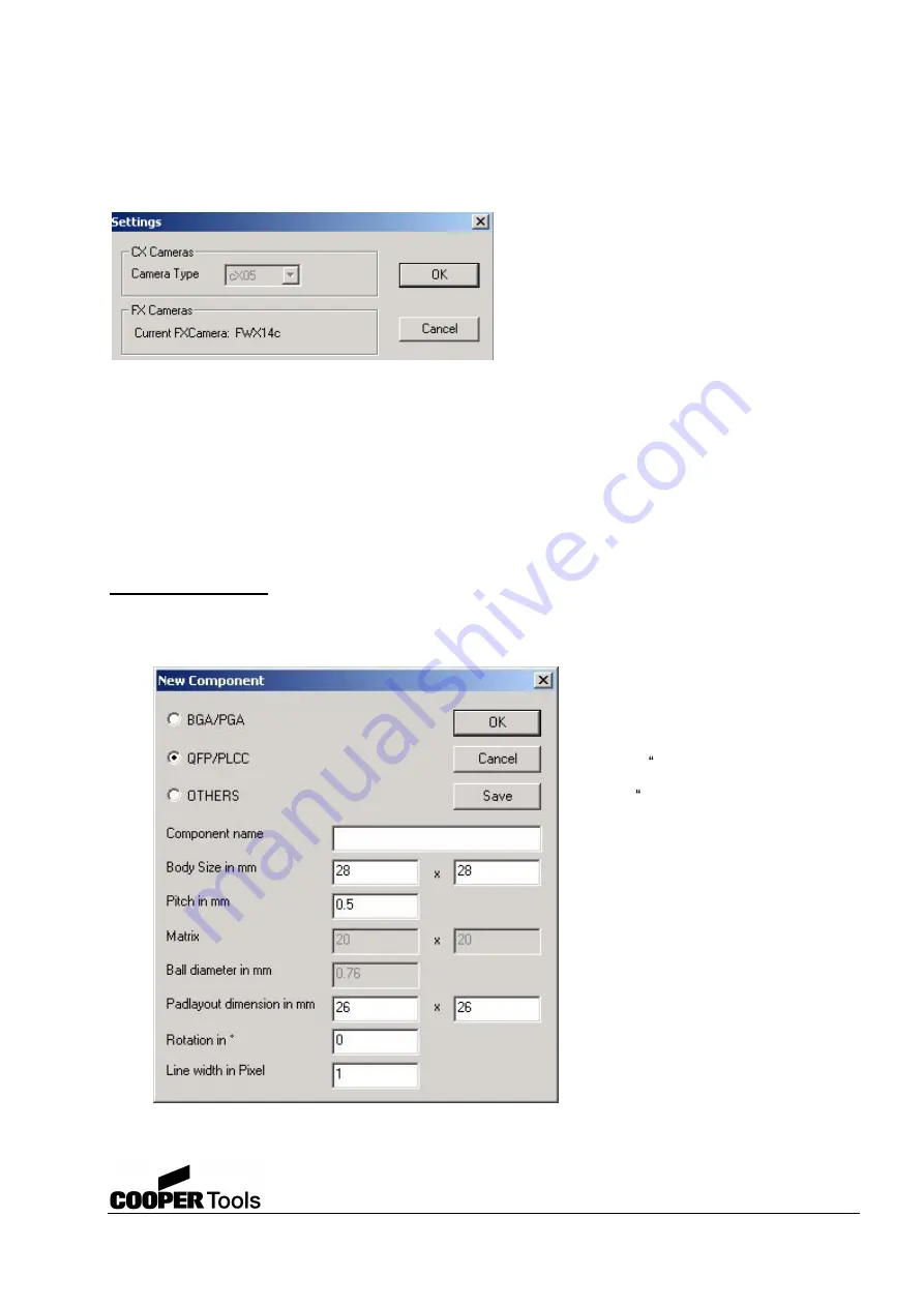
The first time the program is started, there is no 
camera set up for image acquisition. Using the 
Special command, you can choose the camera 
type in the Settings dialog box. To open (initialise) 
the camera, you must make mark it (with a blue 
background) on the list and click the "OK" button. 
The selected camera is then always opened each 
time the program is started.    

Following camera types are supported: 

CX05c 

Colour Digital camera with standard resolution 

CX13c 

Colour Digital camera with high resolution 

For information on the installation of the camera, see section 4.4.   

5.4 

Description of the menu bar and the toolbar  

5.4.1  Menu bar  

Component Library


New 
Opens the New Component dialog box in which you can configure a new component.   

Package dimensions


Pitch


Number of soldered connections in x and y


Ball diameter


Pad dimensions on the circuit board


Rotation of the component


Line width of the frame in pixels


Component name


"

Save  saves the values for a new 

component


"

Cancel  interrupts the function


"

OK" accepts the settings and opens 

the component.


Содержание Weller WQB OPS

Страница 1: ...Camera Positioning System WQB OPS Operating Instruction Version 2 2...

Страница 2: ...amera series 5 4 Description of the menu bar and the toolbar 5 4 1 Menu bar 5 4 2 Toolbar 5 5 Description of the dialog bar 6 Positioning components with the WQB 3000 OPS 6 1 Initialising the position...

Страница 3: ...ponent placement The data transfer from the camera to the PC is made in real time via the IEEE 1394a interface using the OHCI protocol Distortion free pictures of the component to be placed can be ach...

Страница 4: ...f the directives 89 336 EWG und 73 23 EWG 3 System requirements For the usage of the positioning system a commercial standard PC with the following features is required Intel Pentium with at least 1 G...

Страница 5: ...nce with the manufacturer s instructions Choose a suitable PCI expansion slot Unscrew the cover plate for the slot Insert the FireWire interface card in an empty PCI slot in the PC Press the adapter g...

Страница 6: ...ssing software 4 4 1 Installation of the driver for the FireWire interface card Insert installation CD in the drive on the PC Open Hardware wizard on the PC START MY COMPUTER PROPERTIES HARDWARE DEVIC...

Страница 7: ...fter the installation Proceed as follows Has the interface card been fitted to the PC in accordance with the instructions Is the camera connected Is the camera connecting cabled inserted Has the image...

Страница 8: ...e general functions for using the program The individual commands are described in section 5 4 1 Toolbar Here you will find buttons for using the program This toolbar can be toggled on and off The ind...

Страница 9: ...t and click the OK button The selected camera is then always opened each time the program is started Following camera types are supported CX05c Colour Digital camera with standard resolution CX13c Col...

Страница 10: ...eletes the component with a blue background Edit Opens the Edit Component dialog box in which you can change the entries for the selected component Cancel Closes the dialog box without accepting the c...

Страница 11: ...is commissioned for the first time Proceed as follows Insert calibration plate in the WQB 3000 circuit board holder Lock soldering head in the centre of the unit and align the cross wires on the calib...

Страница 12: ...d to which user data can be written The text file is saved in the destination folder set see Settings under the same image name The image formats BMP and JPG default are available see also Save in the...

Страница 13: ...y positioned around the positioning cross If a calibration has not been performed following installation this button is not available The size of the frame depends on the data for the component select...

Страница 14: ...n the destination folder set see Settings under the same image name The following formats are available BMP format JPG format default When a file is saved a dialog box appears in which you can define...

Страница 15: ...must be positioned on the first scale point required and the cross set by clicking the left mouse button Keep the mouse button pressed and drag to the second scale point When the cross is in exactly t...

Страница 16: ...ed and the RGB colour values red green and blue can be changed individually by the user These functions are only available for colour cameras to change the RGB colour values Enable must be selected If...

Страница 17: ...4 x 25 63 x 47 3 0 26 24 x 18 18 x 13 34 x 25 The objective 3 together with the camera 1 is bolt to the base unit with the clamping ring 14 6 1 2 Selecting the vacuum insert 2 different vacuum inserts...

Страница 18: ...he positioning frames During the calibration a conversion factor from image dots in the camera pixels to a measure of length mm is calculated The calibration process is explained in more detail in the...

Страница 19: ...a time delay the vacuum will be switched off and the positioning unit is lifted upwards The component is now exactly placed on the circuit board With the aid of the operating lever 2 the placement he...

Страница 20: ...of any displayed positioning frame didn t lay exactly on the diagonals of the calibration tool Repeat the Camera Adjustment command once more The adjustment must be made with great care by a suitable...

Страница 21: ...The linear guides on the positioning unit are lubricated for life in the factory and do not required any further care 7 3 2 Repair and upkeep Repairs on the positioning system are allowed to do only...

Страница 22: ...25 Hz 1 3 Progressive Scan 1034 x 776 4 6 x 4 6 m2 19 Hz 2 3 Progressive Scan 1392 x 1040 6 7 x 6 7 m2 15 Hz Colour filter RGB Bayer Matrix Optical Interface Objective C Mount Ambient conditions Opera...

Страница 23: ...ng lever 3 Telecentrical objective 4 Positioning unit 5 Precision drive x adjustment 6 Precision drive y adjustment 7 Connecting screw rotating ring 8 Operating lever theta adjustment 9 LED illuminati...

Отзывы: