


23
Cooper Tools GmbH, Carl-Benz-Str. 2, 74354 Besigheim, P.O. Box 1351
Germany, Tel: (07143) 580-0, Fax: (07143) 580108
9.2
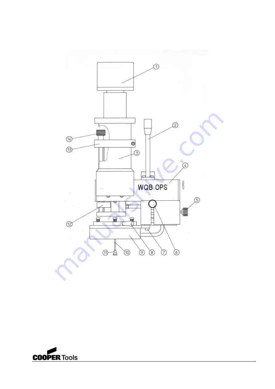
Figures
1
Digital camera
2
Operating lever
3
Telecentrical objective
4
Positioning unit
5
Precision drive, x adjustment
6
Precision drive, y adjustment
7
Connecting screw, rotating ring
8
Operating lever theta adjustment
9
LED illumination module (optional)
10
Vacuum pick up
11
Insert for vacuum pick up
12
Device depth stop
13
Objective clamping ring
14
Adjusting spindle, depth stop


