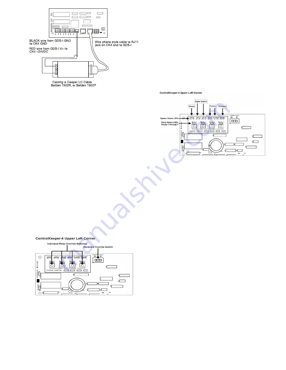
Figure-8 GDS-I Wiring Detail
Applying Power
1. After wiring is complete, make certain to clean panel of all
wire clippings and fragments ensuring that no fragments
get lodged between the circuit board and enclosure.
2. Ensure that there are no loose wires or exposed wires that
could short out.
3. Make certain that the line-voltage section of the enclosure
is closed and secure.
4. Power up the unit. It is recommended that the unit be
cleared of all programming unless the unit has been sent
pre-programmed to you by the factory. To perform this step,
hold down the reset button for about 15 seconds.
5. Please refer to the operation section of this instruction for
information on turning on and off lighting loads. Refer to
the Keeper Enterprise Software manual for information
regarding the programming of the ControlKeeper-4.jumper.
Relay Override Operation
T
he ControlKeeper-4 has two means of override located on the
logic board: individual relay override buttons and a hardware
override switch. It is possible to control lighting loads and
override programming using these override mechanisms.
Figure-10 ControlKeeper-4 Status LEDs
Individual Relay Override Notes
Each relay on the ControlKeeper-4 may be overridden using
the individual relay override switches located at the top left
of the low voltage section. See Figure 9 for location of these
switches. These override switches will toggle the associated
relay’s state with each push of the button. This type of over
ride is temporary in that the override will last until the next
command that the relay is given.
Hardware Override Switch Notes
In addition to the individual relay override switches, there is a
hardware override switch that allows the override of all relays
on the board. If this switch is moved to the ALL ON or ALL OFF
position, all four relays will remain ON or OFF as long as the
switch is in that ALL ON or ALL OFF position. The ON or OFF
state is maintained regardless of programmed state. In order
for relays to run programmed scheduling the hardware override
switch must be in the AUTO or center position. See Figure 9
for location of the hardware override switch.
LED Operation
The ControlKeeper-4 has LEDs for status monitoring. They
consist of System Status LEDs and Relay Status LEDs.
Figure-10 ControlKeeper-4 Status LEDs
System Status LEDs
There are six (6) system status LEDs that are located in the
upper left corner of the ControlKeeper-4. Please refer to Fig
-
ure 10 for location of these status LEDs. These status LEDs
will indicate proper operation or potential problems with the
ControlKeeper-4. Normal Operation includes the following
LED states.
Status LED:
The Status LED will flash ON and OFF con
-
tinuously under normal operation. The LED is an indication of
microprocessor health. If the LED is ON or OFF all the time,
please use the soft reset button on the controller. If the LED
does not resume normal flashing state, contact Technical
Support.
Digital Switch LEDs:
These LEDs, labeled CAN-TX and
CAN-RX, will flash when Digital Switch information is being
passed back and forth between the Digit Switch Gateway and
the ControlKeeper-4.
Power LEDs:
These LEDs, labeled POWER and ISO POWER,
indicate that the ControlKeeper-4 is getting the proper expected
voltage from the transformer. If one or both of these LEDs is not
lit, there is a problem with power to the board. Please contact
Technical Support for further details.
Network LED:
The Network LED should flash only when ac
-
tivity is present on the network wire. If communications com
-
mands are not being transmitted over the network wire from
the Keeper Enterprise Software or broadcast switches and this
LED is flickering, ON constant, or flashing, it is an indication
of noise on the network wire that may interfere with proper
system operation. Please check all network wiring carefully for
shorts to AC Ground if this condition exists. Contact Technical
Support for further troubleshooting help.
-
+
NETWORK
RS232
VDC
DC
GND
+24
CH4
OFF
ON +24
CH3
OFF
ON +24
CH2
OFF
ON +24
CH1
OFF
ON +24
RESET
NET TERM
U28
U25
U26
U22
U24
U1
9
U20
U29
TB7
4
1
2 3
5 6
8
7
J2
J1
U1
8
U27
U23
U21
TB5
TB4
S7
RN1
J3
C26
C20
U1
7
GDS-I
Page 5


