background image

12

START-UP PROCESS

I

t’s now time to start your Water Witch.  Complete the following process to test your unit 

and confirm all components are operating correctly:

STEP 1:


Ensure the project is filled to the required water level.

STEP 2:


Ensure the sensor and solenoid plugs are connected to the correct ports    


of the Control Box (Sensor on the left and Solenoid on the right).

STEP 3:


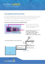
Turn the power and water supplies on and ensure the solenoid flow  


directional arrow is pointing in the same direction as the water flow.

STEP 4:


Lift the Sensor from the balance line and hold it upside down to simulate    


full water level.  The ON and SENSE lights should flash in unison every  


2-4 seconds.

STEP 5:


Turn the Sensor around the right way up to simulate low water level.  The    


ON light should continue to flash every 2-4 seconds and the FILL light  


should be solid.  The Solenoid should also open and add water to the project.  

STEP 6:


Repeat steps 4 & 5 a few times to confirm the unit turns on and  


off correctly.

STEP 7:


Attach the sensor end cap to the sensor balance line and hold the sensor    


cable while you loosen the cable gland.  Slowly lower the Sensor until the    


water flow stops and the ON and SENSE lights flash every 2-4 seconds.     


Re-tighten the cable gland to set the sensor level.

THE SENSOR IS NOW SET AT THE CORRECT LEVEL.  COMPLETE STEPS 8-10  

ON THE FOLLOWING PAGE TO SET THE CORRECT TIME DELAY MODE.

Содержание WaterWitch

Страница 1: ...Product Support Guide Full Electrical Certi cation Inside Outside use ESV160204 C Tick Approval N11116...

Страница 2: ...pes were developed and tested in my shed at home until we had a suitable production model After a few years of production further tweaks and improvements were decided upon The Water Witch was born For...

Страница 3: ...x installation Page 05 Sensor installation Page 06 Solenoid installation Page 08 Alternative installation options Page 10 Start up process Page 12 Test and time delay modes Page 13 Operation of indica...

Страница 4: ...and must be returned upon its request Template updated August 2014 WaterMark Certificate Of Conformity Level 1 This is to certify that Nymet Australia Pty Ltd ABN Head Office Address 1 53 Stanbel Road...

Страница 5: ...ficient overflow provisions to avoid a potential flooding event The Water Witch may not be suitable for installations where the water source is connected to a pressure pump Confirm high and low pressu...

Страница 6: ...ONTROL BOX WS345 Water Witch Control Box SENSOR WS355 Water Witch Sensor Only 5m WS356 Water Witch Sensor Only 20m WS357 Water Witch Sensor Only 30m WS358 Water Witch Sensor Only 40m WS359 Water Witch...

Страница 7: ...least 1 2m above ground level and ensure a consistent power source is within reach of the Control Box power lead The Control Box is approved for indoor and outdoor use However locating the Control Box...

Страница 8: ...the Sensor As the ball intersects the light beam at the top of the Sensor the Control Box recognises the full water level Instead of stopping the flow immediately the TIME DELAY MODE then overfills th...

Страница 9: ...suction and return trench and elbowed up within the equipment area THESE PIPES MUST BE LEVEL TO AVOID AIR LOCKS which will affect flow and performance A 50mm cap is provided to cover the sensor pipe h...

Страница 10: ...r INSTALLATION PROCESS AND CONSIDERATIONS The Solenoid flow is one directional ENSURE THE SOLENOID FLOW DIRECTIONAL ARROW IS POINTED IN THE SAME DIRECTION AS THE WATER FLOW The Solenoid has a 20mm mal...

Страница 11: ...a hard connection An air gap is required to ensure the water from the project cannot contaminate the water source THE FILL FLOW RATE MUST NOT EXCEED THE RATE THE BALNCE LINE TRANSFERS WATER INTO THE P...

Страница 12: ...he Sensor end cap Run the Sensor cable through appropriately sized conduit to ensure the Sensor can be accessed for serviceability and replaced if required Small debris capable of affecting sensor per...

Страница 13: ...kely result in severe pump equipment and site damage The water level in the trough may increase dramatically during a significant rainfall event or heavy bather load The trough capacity above the mini...

Страница 14: ...ate full water level The ON and SENSE lights should flash in unison every 2 4 seconds STEP 5 Turn the Sensor around the right way up to simulate low water level The ON light should continue to flash e...

Страница 15: ...L cycle The four time delay settings are controlled by the position of dip switches inside the bottom right corner of the Control Box STEP 8 TURN THE POWER SUPPLY OFF AND UNPLUG THE WATER WITCH POWER...

Страница 16: ...t the correct height ON light is flashing every 2 4 seconds and the FILL light is solid The Water Witch is in TEST MODE and is adding water because it believes the water level is low ON and FILL light...

Страница 17: ...following tables to identify the fault being experienced and the action required to remedy the fault WATER WILL NOT TURN ON Light Display Possible Fault Remedy ON SENSE Sensor debris may be impeding f...

Страница 18: ...he flow directional arrow on the Solenoid is pointing in the same direction as supply flow Reinstall if required Solenoid wire is damaged or does not have a positive connection to control box Ensure t...

Страница 19: ...most likely too high Water pressure is too high Install a Pressure Limiting Valve between supply tap Solenoid to reduce pressure WATER WILL NOT TURN OFF Be aware there is a tiny spring and rod inside...

Страница 20: ...plate from bottom of Sensor Remove ball to clean the inside of Sensor Sensor or Control Box has failed Return Control Box to Test Mode and complete the following to confirm fault Hold Sensor in uprig...

Страница 21: ...are corroded damaged or blown There are markings caused by water ingress You will most likely need to replace the Control Box if you are experiencing any of the above faults If the Control Box housin...

Страница 22: ...trol Box as required Annually Remove the solenoid pre filter to clear any debris or contaminant Maintenance checks should be conducted more regularly for commercial applications Product Water Witch El...

Страница 23: ...ditions which may impede or obstruct the correct functioning of the unit Warranty claims are to be lodged at www cookeindustries com au warranty Please note the user must submit the serial number and...

Страница 24: ...Cooke Industries P 1300 652 076 E info cookeindustries com au cookeindustries com au...

Отзывы: