background image


Safety and Operating Instructions 

for Frequency Converters


according to Low Voltage Directive 73/23/EEC 

 
1.  General 
 
During  operation,  frequency  converters  can  have  live, 
rotating or moving parts and their surfaces may become hot, 
depending on the protection class involved. 
 
There is a risk of severe physical injury or material damage 
if any of the covers are removed or the unit is installed, used 
or operated incorrectly. 
 
Further details are given in the documentation. 
 
All system design, transport, installation, commissioning and 
maintenance work must be carried out by qualified specialist 
personnel  (according  to  IEC  60364,  CENELEC  HD  384  or 
DIN  VDE  0100  and  IEC  60664  or  DIN  VDE  0110  and 
national safety regulations). 
 
Qualified  specialist  personnel  in  the  sense  of  these  safety 
instructions are persons who are experienced in the system 
design,  installation,  erection,  commissioning  and  operation 
of  the  product  and have  the qualifications required  for  such 
work. 
 
2.  Correct use 
 
Converters are  intended  for  installation  in  electrical  plant  or 
machinery. 
 
When  installed  in  machines  the  converter  may  not  be 
commissioned  (i.e.  operation  of  the  converter  may  not  be 
started) until it is evident that the machine complies with EC 
directive 

98/37/EC 

(Machine 

Directive) 

(formerly 

89/392/EEC). Also EN 60204 must be observed. 
 
Commissioning  (i.e.  operation)  is  only  permitted  in 
compliance with the EMC directive (89/336/EEC). 
 
Our  converters  satisfy  the  requirements  of  low  voltage 
directive 73/23/EEC. The standards of the series EN 50178 / 
DIN VDE 0160 in conjunction with EN 60439-1 / VDE 0660 
Part 500 and EN 60146 / VDE 0558 are applicable to drive 
converters. 
 
The technical data and the connection conditions are shown 
on the rating plate and in the documentation. They must be 
observed. 
 
3.  Transport and storage 
 
The  instructions  for  transport,  storage  and  correct  handling 
must be observed. 
 
Climatic  conditions  are  to  be  maintained  according  to 
EN 50178. 


4.  Installation 
 
The installation and cooling must be in accordance with the relevant 
documentation. 
 
All  converters  must  be  protected  against  undue  mechanical  shocks 
or  stress.  In  particular  no  components  may  be  bent  and/or  no 
insulation spacing may be altered during transport and handling. Do 
not touch electronic components or contacts. 
 
Converters  contain  components  susceptible  to  electrostatic 
discharge  (ESD),  which  are  easily  damaged  by  static  electricity  or 
incorrect handling. Do not damage mechanically or destroy electrical 
components (health hazard possible). 
 
5.  Electrical connection 
 
The  appropriate  national  safety  regulations  (e.g.  BGV  A3)  must  be 
observed  when  working on  converters,  which  are  connected,  to  the 
electricity supply.  
 
The  electrical  installation  must  be  executed  in  accordance  with  the 
relevant  regulations  (e.g.  cable  cross-sections,  fuses,  earthing). 
Additional instructions are given in the documentation. 
 
Instructions  on  EMC  compliant  installation,  such  as  screening, 
earthing,  filters  and  cable  routing,  are  also  given  in  the  converters 
documentation. These also apply to converters bearing the CE mark. 
Compliance  with  the  limits  specified  in  EMC  legislation  is  the 
responsibility of the plant or the machinery manufacturer. 
 
6.  Operation 
 
If necessary, plant or machinery in  which converters are fitted must 
be  equipped  with  additional  monitoring  and  safety  facilities  in 
accordance  with  the  relevant  regulations,  e.g.  the  law  on  technical 
equipment, the appropriate safety regulations etc. 
 
Do  not  touch  any  parts  of  the  equipment  which  may  be  live  or  any 
power  connections  even  after  the  converter  has  been  isolated  from 
the electricity supply, as capacitors may remain charged. Follow the 
instructions given on warning labels.  
 
All covers and doors must be kept closed during operation. 
 
7.  Service and maintenance 
 
All instructions given in the documentation must be observed. 
 
KEEP THESE SAFETY INSTRUCTIONS IN A SAFE PLACE 

Содержание 700.002 735

Страница 1: ...Ethernet Option Board LV7000 Order No 700 002 735 Issue 06 08 AE01 Operating Manual ...

Страница 2: ...nd correct handling must be observed Climatic conditions are to be maintained according to EN 50178 4 Installation The installation and cooling must be in accordance with the relevant documentation All converters must be protected against undue mechanical shocks or stress In particular no components may be bent and or no insulation spacing may be altered during transport and handling Do not touch ...

Страница 3: ...ontrol provided by LV7000 Frequency Converters The Operating manual will provide you with the necessary information about the installation commissioning and operation of Converteam Frequency Converters We recommend that you carefully study these instructions before powering up the frequency converter for the first time ...

Страница 4: ...nverter it is however not possible to describe all conceivable applications and to provide exhaustive information and guidance for engineering configuration commissioning etc Should you have any questions concerning Converteam frequency converters or should you need any assistance we hence recommend that you contact our drive specialists Expressions used Note Notes separate important information f...

Страница 5: ...llation are adhered to in conjunction with the engineering and installation of the overall system The following information is to help to assess the risks related to the use of the unit It is the user s responsibility to take any measures suitable to address these risks Under incorrect or unwanted conditions the motor can work at an incorrect speed at a high overspeed and or in the wrong direction...

Страница 6: ...y damages which might result from any defects in the documentation The user is to be solely responsible for the proper and correct use of the LV7000 frequency converters Converteam disclaims any liability whatsoever for improper or incorrect handling Process information and circuit details contained in the manuals shall be deemed as being suggestions only which shall be subject to verification by ...

Страница 7: ...1 400001 402000 and 402200 410000 Application ID 4 5 4 5 2 10501 10533 10601 10633 ID MAP 4 6 4 5 3 10001 10033 10101 10133 Index MAP 4 7 4 5 4 402200 410000 FB Process Data Out Read 4 7 4 5 5 402200 410000 FB Process Data In Read Write 4 7 4 5 6 10301 10333 Measurement Table 4 8 4 6 Input Registers 3x 4 8 4 6 1 Operation Day Counter 30001 30007 4 8 4 6 2 Reset table Operation Day Counter 30101 30...

Страница 8: ...Contents Ethernet Option Board 700 002 735 AE01 ...

Страница 9: ... on the sticker attached to the board or by using the Converteam IP tool software NCIP Config In a local network the user can define IP addresses as long as all units connected to the network are given the same network portion of the address For more information about IP addresses contact your Network Administrator Overlapping IP addresses cause conflicts between appliances For more information ab...

Страница 10: ...1 Introduction 1 2 Ethernet Option Board 700 002 735 AE01 ...

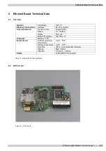
Страница 11: ...er cable Foiled CAT5e Speed 10 100 Mb Duplex half full Communications Default IP address 192 168 0 10 Protocols Modbus TCP Ambient operating temperature 10 C 50 C Storing temperature 40 C 70 C Humidity 95 no condensation allowed Altitude Max 1000 m Environment Vibration 0 5 G at 9 200 Hz Safety Fulfils EN50178 standard Table 2 1 Ethernet Board Technical Data 2 2 OPT CI card Figure 2 1 OPT CI card ...

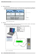
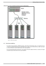
Страница 12: ...features of these two use cases are presented in the pictures below 1 Human to machine Graphical User interface relatively slow communication Figure 2 3 HMI communication 1 Physical 2 Data Link 3 Network 4 Transport 5 Session 6 Presentatio 7 Applicatio Ethernet Physical Layer Ethernet Data Link Layer IP TCP UDP Protocol Layer HTTP DHCP Modbus TCP Ethernet IP etc 1 Physical 2 Data Link 3 Network 4 ...

Страница 13: ...upports 10 100Mb speeds in both Full and Half duplex modes The boards must be connected to the Ethernet network with a shielded CAT 5e cable Use a so called crossover cable if you want to connect the Ethernet option board directly to the master appliance Use only industrial standard components in the network and avoid complex structures to minimize the length of response time and the amount of inc...

Страница 14: ...2 Ethernet Board Technical Data 2 4 Ethernet Option Board 700 002 735 AE01 ...

Страница 15: ...nstalling the Ethernet Option Board in a Converteam LV7000 Unit Note MAKE SURE THAT THE FREQUENCY CONVERTER IS SWITCHED OFF BEFORE AN OPTION OR FIELDBUS BOARD IS CHANGED OR ADDED A Converteam LV7000 frequency converter B Remove the cable cover C Open the cover of the control unit ...

Страница 16: ...oard in slot D or E on the control board of the frequency converter Make sure that the grounding plate see below fits tightly in the clamp E Make a sufficiently wide opening for your cable by cutting the grid as wide as necessary F Close the cover of the control unit and the cable cover ...

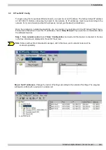
Страница 17: ...ully you can launch it by selecting it in the Windows Start menu Follow these instructions to set the IP addresses Select Help Manual if you want more information about the software features Step 1 Scan network nodes Select Scan Configuration and wait until the devices connected to the bus in the tree structure are displayed on the left of the screen Note Some switches block broadcast messages and...

Страница 18: ... OPT CI Option Board program with the NCIP Config Tool In some cases it may be necessary to update the option board s firmware Differing from other Converteam option boards the Ethernet option board s firmware is updated with the NCIP Config software To start the firmware update scan the nodes in the network according to the instructions in section 3 2 Once you can see all nodes in the view you ca...

Страница 19: ... you can choose a new firmware packet is displayed Send the new firmware packet to the option board by checking its box in the VCN Packet field at the right corner of the table view After selecting all nodes to be updated by checking the boxes send the new firmware to the board by selecting Configuration then Configure 2 1 ...

Страница 20: ...3 Installation 3 6 Ethernet Option Board 700 002 735 AE01 ...

Страница 21: ...server answers client queries with response messages The term client can refer to a master device that runs queries Correspondingly the term server refers to a slave device that serves the master device by answering its queries Both the request and response messages are composed as follows Byte 0 Transaction ID Byte 1 Transaction ID Byte 2 Protocol ID Byte 3 Protocol ID Byte 4 Length field upper b...

Страница 22: ...t 10001 1FFFF Read Table 4 1 Supported Registers Name Size Modbus address Type Input Registers 16bit 30001 3FFFF Read Holding Register 16bit 40001 4FFFF Read Write Coils 1bit 00001 0FFFF Read Write Input discretes 1bit 10001 1FFFF Read Table 4 2 Supported Registers 4 3 Coil 0x01 Register The Coil register represents data in a binary form Thus each coil can only be in mode 1 or mode 0 Coil register...

Страница 23: ...nergy trip counter can be reset by entering 1 as the value of the coil in request When the value 1 is entered the device resets the counter However the device does not change the Coil value after reset but maintains the 0 mode Address Function Purpose 0017 Clear OpDay Clears OpDay counter 0018 Clear MWh Clears MWh counter Table 4 5 Counters The following table represents a MODBUS query that resets...

Страница 24: ... word bit 6 10008 Flux Ready Status word bit 7 10009 Manufacturer reserved Table 4 7 Status Word Structure The following tables show a MODBUS query that reads the entire status word 8 input discretes and the query response Query 0x00 0x00 0x00 0x00 0x00 0x06 0x01 0x02 0x00 0x00 0x00 0x08 Data Purpose 0x00 Transaction ID 0x00 Transaction ID 0x00 Protocol ID 0x00 Protocol ID 0x00 Length 0x06 Length ...

Страница 25: ...se 0001 2000 Converteam Application ID s 2001 2099 FB Process Data IN 2101 2199 FB Process Data OUT 2200 10000 Converteam Application ID s 10001 10033 Index Map 10101 10133 Index Map Read Write 10301 10333 Measure Table 10501 10533 IDMap 10601 10633 IDMap Read Write 10634 65535 Not Used Table 4 11 Holding Registers 4 5 1 400001 402000 and 402200 410000 Application ID Application ID s are parameter...

Страница 26: ...alization Once the IDMap address range has been initialized with any parameter ID number the parameter value can be read and written in the IDMap Read Write address range address IDMap address 100 Address Data 410601 Data included in the parameter ID 700 410602 Data included in the parameter ID 702 410603 Data included in the parameter ID 707 410604 Data included in the parameter ID 704 Table 4 13...

Страница 27: ... 000 2104 FB Process Data out 1 See Appendix 1 2105 FB Process Data out 2 See Appendix 1 2106 FB Process Data out 3 See Appendix 1 2107 FB Process Data out 4 See Appendix 1 2108 FB Process Data out 5 See Appendix 1 2109 FB Process Data out 6 See Appendix 1 2110 FB Process Data out 7 See Appendix 1 2111 FB Process Data out 8 See Appendix 1 Table 4 14 Process Data Out 4 5 5 402200 410000 FB Process ...

Страница 28: ...otor Nom Voltage Unsigned integer 10316 Motor Nom Freq Unsigned integer 10317 Motor Nom Speed Unsigned integer 10318 Current Scale Unsigned integer 10319 Motor Current Limit Unsigned integer 10320 Deceleration Time Unsigned integer 10321 Acceleration Time Unsigned integer 10322 Freq Max Unsigned integer 10323 Pole Pair Number Unsigned integer 10324 Ramp Time Scale Unsigned integer 10325 Ms Counter...

Страница 29: ...ss Purpose 30301 Energy 30302 Format 30303 1 kWh 2 MWh 3 GWh 4 TWh Table 4 20 Reset table Energy Counter 4 6 5 Error History 30401 30417 The error history can be viewed by reading from the address 30401 onward The errors are listed in chronological order so that the latest error is mentioned first and the oldest is mentioned last The error history can contain 16 errors at any time The error histor...

Страница 30: ...4 Modbus TCP 4 10 Ethernet Option Board 700 002 735 AE01 ...

Страница 31: ... 1 Frequency Converter Settings Select fieldbus as the active control bus For more information see the Converteam LV7000 Operating Manual section 7 3 3 5 2 Master Unit Programming Write a FB Control Word address 42001 of value 1Hex The frequency converter is now in the RUN mode Set the FB Speed Reference address 42003 value of 5000 50 00 The engine is now running at a 50 speed Write a FB Control W...

Страница 32: ...5 Start up Test 5 2 Ethernet Option Board 700 002 735 AE01 ...

Страница 33: ...board will set the fieldbus error 53 in the frequency converter Confirm the error by pressing the reset button Card slot error 54 may be due to a faulty board a temporary malfunction of the board or a disturbance in the environment 6 2 Modbus TCP This section discusses Modbus TCP error codes used by the OPT CI board and possible causes of the errors Code Modbus exception Possible cause 0x01 Illega...

Страница 34: ...6 Error Codes and Errors 6 2 Ethernet Option Board 700 002 735 AE01 ...

Страница 35: ...he Multipurpose Control application has a selector parameter for every Process Data The monitoring values and drive parameters can be selected using the ID number see LV7000 All in One Application Manual Tables for monitoring values and parameters Default selections are as in the table above Process Data IN Master to Slave Control Word Reference and Process Data are used with all in One applicatio...

Страница 36: ... Redistributions in binary form must reproduce the above copyright notice this list of conditions and the following disclaimer in the documentation and or other materials provided with the distribution 3 The name of the author may not be used to endorse or promote products derived from this software without specific prior written permission THIS SOFTWARE IS PROVIDED BY THE AUTHOR AS IS AND ANY EXP...

Страница 37: ......

Страница 38: ...7660 Converteam India Private Ltd Unit No 1003 Tower B 10th Floor Millennium Plaza Sector 27 Gurgaon 122 002 Haryana India Tel 91 124 4200190 Fax 91 124 4200194 Converteam UK Ltd Boughton Road Rugby Warwickshire CV21 1BU UK Tel 44 0 1788 563 563 Fax 44 0 1788 560 767 Converteam Power Conversion Shanghai Co Ltd Building 4 No 333 Lane 2888 Huaning Road Minhang District 201109 Shanghai China Tel 86 2...

Отзывы: