


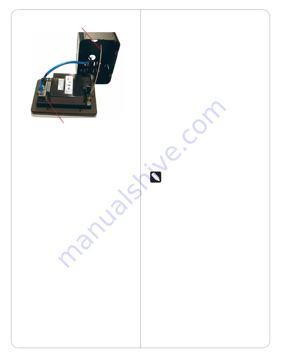
Figure 8. WiFi with PoE
Attach the Door Station
After the back box, all wiring, cables, and antennas
are installed, carefully insert the Door Station into the
back box and the wall:
1
On the front of the faceplate remove the tape
that covers the camera hole.
2
Align the five (5) holes and use the security
screws provided to attach the Door Station to
the back box.
3
To prevent dust from getting inside the Door
Station, make sure the rubber gasket on the
inside panel of the Door Station completely
covers and seals the Door Station’s faceplate
against the back box.
4
Attach the faceplate and use the screw from the
bottom to secure it.
Configure the Door Station
To configure the Door Station in Composer Pro:
1
Open Composer Pro.
2
Double-click the
Door Station
driver to add it to
a room in the project.
3
Identify the device to the project.
(WiFi only) For your convenience, the Door Station
driver includes a meter to check WiFi signal strength.
Use System Manager in Composer Pro to configure
the WiFi parameters. See the
Composer Pro User
Guide
for details.
Reset/Factory Restore the Door Station
To reset or factory restore the Door Station:
1
Remove the faceplate and pull the Door Station
out from the back box just enough to expose the
Reset button (see Figure 2).
2
While powered press the
Reset
button on the
bottom of the Door Station to reset or restore
the Door Station.
• Quick press
. Press to reset the Door Station.
• Long press
. Press until the button on the
faceplate begins to blink rapidly. At that time, the
factory restore starts. This action restores the
Door Station to its factory default settings.
3
When you are finished, insert the Door Station
back into the back box and reattach the
faceplate.
WiFi Antennas (Optional)
NOTE
:
Control4 does not recommend to install
the Door Station using WiFi. The best option is
to use Ethernet.
Two (2) types of WiFi antenna kits are available for
purchase: 26cm (dipole, best performance) or 3m
(when you need to install the wire further away from
the Door Station for a better WiFi signal).
• Antenna Kit—WiFi/ZigBee 2.4GHz, 26cm
(C4-
AK-26cm, sold separately). Recommended for
walls that do not have thick concrete or metal.
See Figure 9 and “WiFi Antenna Kit Installation”
for details.
• Antenna Kit—WiFi/ZigBee 2.4GHz, 3m
(C4-AK-
3M, sold separately). Extend the range when
walls have thick concrete or metal. See Figure 10
and “WiFi Antenna Kit Installation” for details.
7
WiFi Antenna
Ethernet and PoE Connection


