


W415-1080 / B / 08.28.13
21
IOM
DO NOT CONNECT FURNACE TO A CHIMNEY OR FLUE SERVING OTHER APPLIANCES OR A
SOLID FUEL BURNING APPLIANCE.
WARNING
!
!
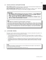
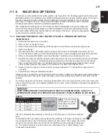
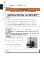
9.1 VENT
TERMINATION
*3"
(76mm)
MIN.
12"
(305mm)
MIN.
INTAKE
EXHAUST
GRADE
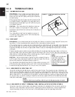
*18" (457mm) MIN. FOR COLD
CLIMATES (SUSTAINED 0°F (-18°C)
FOR 24 OR MORE CONSECUTIVE
HOURS
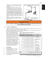
FIGURE 8 - STANDARD (STRAIGHT) HORIZONTAL
VENT DETAIL
lengths, be sure to count all termination
fi
ttings
in addition to counting the concentric vent as a
straight pipe.
Take the building orientation and the presence
of other buildings or other nearby structures into
consideration when planning the venting system
location. Certain external structures could create
air turbulence around the vent termination lead-
ing to downdrafts and similar venting problems. In
windy and hill locations, roof venting may improve
operations. Maximum venting length is based on 30
mph (48 km) winds, areas where higher gusts are
dominant it is suggest to shorten the horizontal vent
length.
The vent and combustion air intake shall be in-
stalled so that both are located in the same wind
pressure zone.
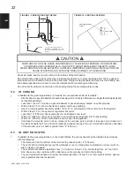
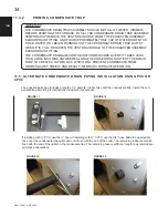
Horizontal vents should pass through the exterior wall. Figure 8 shows a standard horizontal vent detail. Termi-
nate the vent approximately 8” (203 mm) or more from the wall.
Exterior vent pipe greater than 24” (610 mm) should be insulated with ½” (13 mm) insulation to prevent mois-
ture from freezing within the pipe and accumulating.
Size the exhaust pipe as speci
fi
ed in
Table 4 - Direct and Non-Direct Vent
Lengths
. This table lists the maximum
allowable length of pipe with respect to
the number of 90° elbows used. For the
purposes of this calculation, one 90°
elbow is equivalent to two 45° elbows.
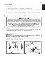
Avoid locating the terminal in locations
where dripping condensate may cause
problems such as sidewalks, patios,
above planters, near windows where
exhaust gases may cause fogging, etc.
Avoid locating the termination too close
to shrubs and other vegetation. The
condensate may stunt or kill them.
EQUIVALENTS
Short Radius Elbow = 7’ (2.13 m)
Medium Radius Elbow = 2.5’ (.76 m)
Long Radius Elbow = 5’ (1.52 m)
Vent lengths that require more than
6-90° elbows, add listed equivalents for
every elbow up to the maximum allow-
able vent length.
TABLE 4 - DIRECT AND NON-DIRECT VENT LENGTHS
Maximum Allowable Length Of Exhaust Or Intake. Minimum Vent Length 15 ft.
(4.6 m) or equivalent.
INPUT
K/Btu/hr
PIPE
SIZE
NUMBER OF 90° ELBOWS
NOTES
0
1
2
3
4
5
6
60
1½
60*
55
50
45
40
35 30
1. Count concentric vent
fi
tting as straight pipe.
2. Use medium or long
sweep elbows where
possible.
3. One 90° elbow is
equivalent to two 45°
elbows.
4. For direct vent, the
listed lengths are
allowed for each vent
(intake and exhaust).
5. For non-direct vent,
the listed lengths are al-
lowed for exhaust. The
intake should have a
1½” or 2” snorkel intake
fi
tting. (Figure 7)
2
75*
70
65
60
55
50 45
3
100*
95
90
85
80
75 70
80
2
50*
45
40
35
30
25 20
3
100*
95
90
85
80
75 70
100
2
50*
45
40
35
30
25 20
3
100*
95
90
85
80
75 70
120
3
100*
95
90
85
80
75 70
NOTE
* Maximum allowable vent (intake and exhaust) length.
When 1½” or 3” pipe is used, exit the cabinet with 2” pipe. Reduce or in-
crease immediately after exiting the cabinet on both intake and exhaust.
H12.4.3
Содержание C97 Series
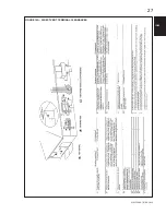
Страница 27: ...W415 1080 B 08 28 13 27 IOM FIGURE 14A DIRECT VENT TERMINAL CLEARANCES ...
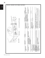
Страница 28: ...W415 1080 A 08 28 13 28 IOM IOM FIGURE 14B NON DIRECT VENT TERMINAL CLEARANCES ...
Страница 58: ...W415 1080 A 08 28 13 58 IOM IOM 23 0 SERVICE HISTORY ...
Страница 72: ...W415 1080 A 08 28 13 ...


