


W415-1080 / A / 08.28.13
20
IOM
IOM
9.0 VENTING GUIDELINES
FAILURE TO FOLLOW ALL VENTING GUIDELINES MAY RESULT IN ERRATIC FURNACE
OPERATION, FREEZE-UP OF THE EXHAUST AIR PIPING.
CAUTION
!
!
READ AND FOLLOW ALL INSTRUCTIONS IN THIS SECTION. FAILURE TO PROPERLY VENT THIS
FURNACE CAN CAUSE CARBON MONOXIDE POISONING OR AN EXPLOSION OR FIRE RESULTING
IN PROPERTY DAMAGE, PERSONAL INJURY OR LOSS OF LIFE.
WARNING
!
!
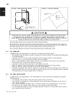
NOTE
• Combustion air intake and exhaust termination should be inspected periodically to ensure they are clear of
obstructions. i.e. vegetation, debris, snow, etc.
• Accumulation of snow around the combustion air intake and exhaust termination may have
negative effects on appliance operation and/or performance. Snow accumulation should be
considered when locating combustion air intake and exhaust terminations.
ATTENTION
:
UPFLOW VENTING RIGHT, MUST DRAIN ON LEFT SIDE.
IMPORTANT
:
•
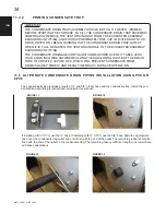
CLEAN AND DE-BURR ALL PIPE CUTS. THE SHAVINGS MUST NOT BE ALLOWED TO
BLOCK THE EXHAUST, COMBUSTION AIR INLET OR CONDENSATE DRAIN LINES.
• EVEN UNCUT FULL LENGTH SECTIONS PRODUCE SHAVINGS DURING ASSEMBLY
THAT COULD BLOCK CONDENSES TO DRAINAGE.
• THE EXHAUST VENT MUST BE SUPPORTED APPROPRIATELY PRIOR TO IT BEING
FITTED TO THE EXHAUSTER. UNDER NO CIRCUMSTANCES SHALL THE EXHAUSTER
BEAR ANY WEIGHT OF THE VENTING SYSTEM.
• IF THE PIPE AND FITTINGS ARE TO BE OTHER THAN PVC, USE THE PROPER
CLEANER, PRIMER AND CEMENT FOR THE DISSIMILAR MATERIALS.
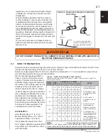
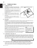
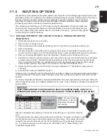
• Venting may be vertical or horizontal.
• Minimum vent length - 15 total equivalent feet.
(See Venting Table)
• Horizontal piping must slope back towards the furnace at a minimum rate of ¼” (6.4 mm) to the foot (305
mm), so that condensate drains towards the furnace.
• Horizontal runs must be supported at least every 3 feet (914 mm). Horizontal sections must not dip or sag.
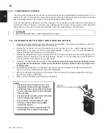
• All vent runs through unconditioned space where freezing might occur should be insulated with 1” (25 mm) thick,
medium density, foil-faced Fiberglass insulation. An equivalent “arm-a-
fl
ex” or “rub-a-tex” may also be used as
long as there is no heat tape applied to the vent pipe. For horizontal runs where water may collect, wrap the vent
pipe with self regulating 3 or 5 watt heat tape. The heat tape must be CSA, UL, or ULC listed and installed per the
manufacturer’s instructions.
This includes travel through unconditioned attic space.
• DO NOT COMMON VENT WITH ANY OTHER APPLIANCE.
• If venting vertically, do not vent up a chimney serving another appliance or install in a chase with a metal or
high temperature plastic pipe from another gas or fuel burning appliance unless the required clearances to
combustibles can be maintained between the furnace venting system and other pipes.
All exhaust piping must be installed in accordance with CAN/CGA-B149.in Canada; the latest edition of Na-
tional Fuel Gas Code, NFPA 54 / ANSI Z223.1 in the United States, as well as in accordance with local codes.
Size the combustion air and exhaust piping in accordance with Table 4. When calculating allowable vent
Содержание C97 Series
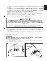
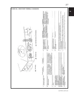
Страница 27: ...W415 1080 B 08 28 13 27 IOM FIGURE 14A DIRECT VENT TERMINAL CLEARANCES ...
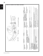
Страница 28: ...W415 1080 A 08 28 13 28 IOM IOM FIGURE 14B NON DIRECT VENT TERMINAL CLEARANCES ...
Страница 58: ...W415 1080 A 08 28 13 58 IOM IOM 23 0 SERVICE HISTORY ...
Страница 72: ...W415 1080 A 08 28 13 ...


