PT-S959SDLX / PT-S959SDLXC Series User’s Manual
27
3
3
.0
0
3
9
.4
0
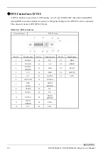
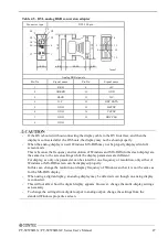
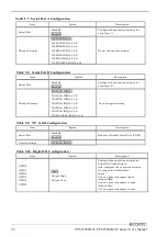
Table 4.5. DVI–analog RGB conversion adapter
Connector type
DVI-I 29 pin
C5
C4 C2
C3 C1 6
16
24 8 1 11
5 15
17 1
10
15.00 6.20 30.00 5.80
[mm]
[mm]
Analog RGB signals
Pin No.
Signal name
Pin No.
Signal name
1
RED
9
+5V
2
GREEN
10
GND
3
BLUE
11
N.C.
4
N.C.
12
DDC DATA
5
GND
13
HSYNC
6
GND
14
VSYNC
7
GND
15
DDC CLK
8
GND
-
If the OS is booted without connecting the display cable to the DVI interface, and then the
display is connected after the OS boots, the display may not be shown properly.
-
When the analog display is used, Windows MS-DOS may not be properly displayed in full-
screen mode.
This is because the frequency and resolution of Windows and MS-DOS (full-screen display) are
the same due to the screen settings while the display parameters are different.
For display, as only one parameter can be stored for one frequency or resolution, only either of
Windows or MS-DOS screen can be displayed properly.
In this case, change the resolution or display frequency of Windows so that it is not the same as
for the MS-DOS display.
-
When using a digital display, an analog display may be detected even though no analog display
is connected.
-
This will not affect how the digital display appears. However, change the multi -display settings
as necessary.
-
To change the settings from digital output to analog output, change the settings from the
standard Windows properties screen.


