4
9. Installation
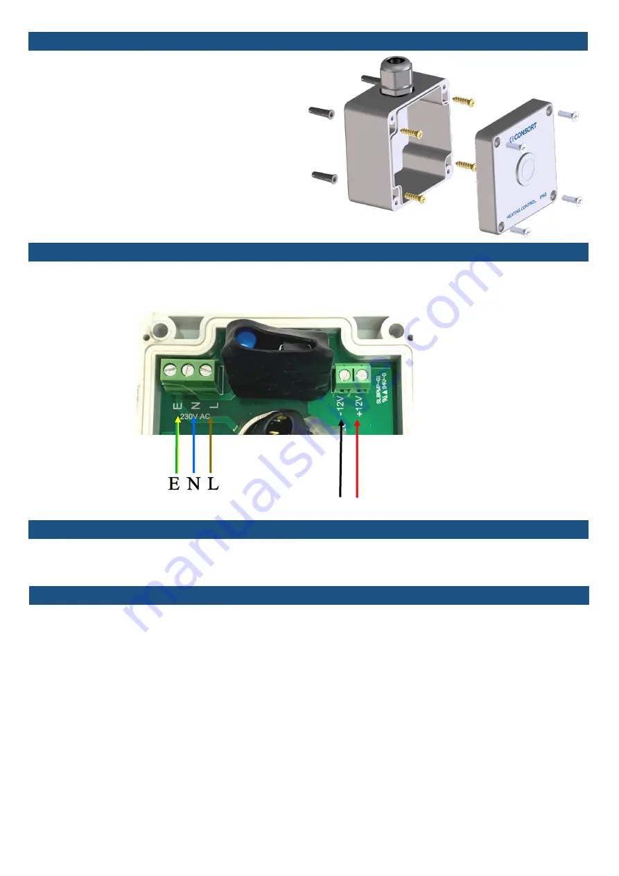
The controller can be powered by either mains
240VAC 50Hz or 12VDC. The power consumption is less
than 1W. Do not connect mains voltage to 12V
terminals, this will damage the controller. The
maximum size wire that can be used is 1mm
2
. This can
be twin and earth or standard flex . Do not overtighten
the connector screws. Take care not to damage the
components when connecting the cables.
The gland outlet can be positioned at the top or
bottom of the controller this will depend on the
installation.
The controller comes with 4 wall plugs suitable for a
5mm hole and 4 screws. See the diagram on the right
for installation assembly.
12. Self Diagnostic
When powering the controller with 12Vdc, the installation must comply with the Separated Extra Low Voltage (SELV)
requirements. When powered by 12VDC, please ensure that the power supply is suitable for 12V 0.1A. For 12VDC
power connect positive wire to terminal 12V and negative to terminal marked –12V.
11. Connection to 12V DC
The controller is equipped with a self diagnostic software that will check functionality of all main components. If
there is a fault with any part of the controller or the controller is operating outside of the temperature limits, the light
indicator will flash red . If this happens, controller will not function in order to protect itself and the heaters.
13. Pairing with heaters
In order to pair your appliance with the controller you must do the following:
Ensure the controller is in the OFF position (the light indicator is off or red).
Turn power to the appliance ON.
Within 20 seconds, press and hold the ON button on the controller until the light indicator begins to flash yellow.
After the pairing is finished, the light indictor will change to green.
If the pairing was successful, the appliance should emit heat. It can take up to 4 seconds.
After 4 seconds, the appliance will be switched off.
The appliance is now ready to be used.
Mains Connection
230/240V AC 50Hz
+
-
12V DC


