VTop Control Valves
M/VTOP-M/E ed. 01 2020
3.5.3.5 – FIELDBUS INTERFACE (Optional on request)
Optionally, a field bus interface can be adapted to the AMS actuator by connecting a terminal block or an external socket.
(additional assembly manual available for fieldbus AMS).
3.6 – ACCESSORIES
3.6.1 – ANTI-CONDENSATE RESISTOR (Optional on request)
The PSL-AMS actuators can be equipped with an anti-condensate resistor, when using the actuators in environments
with high temperature fluctuations or high humidity, you are advised to use an anti-condensate resistor to prevent
condensate formation
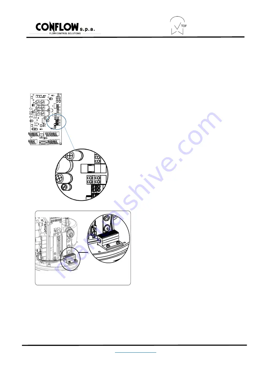
Figure 7: Resistor connection
In PSL-AMS actuators, the resistor is powered using
the actuator power supply, so there is no need to be
powered separately. To replace the resistor, connect
two cables to the terminal of the motherboard as
represented
in the image on the left.
The anti-condensate resistor is available in two different
versions (for 24 VAC/DC or 115-230 VAC). Choose the
voltage of the actuator based on the voltage.
Assembly of the resistor must be carried out in the position
indicated on the base, using the screws supplied, turn the
cable in such a manner they are not crushed by the main
cover and not touched by movement of the components
inside the actuator.
3.6.2 – ADDITIONAL LIMIT SWITCH SETTING (Optional on request)
In the PSL-AMS there are already two position feedback switches, available as a default option. They are clean
exchange contacts.
The silver-plated contacts are available (for currents between 10 Ma and 5 A, max 230 V or gold-plated contacts (for
currents between 0.1 mA and 30 Ma, max 30V). Then connect to terminals 18/19 and 20/21
Figure 8: Resistor assembly


