9
IOM CLUSTER BAR MANUAL
964000.5.0
2.0 Installation
1/4” Gap Max
2-3/4”
1-1/8”
7/8”
Figure 14
1”
1”
1-1/8”
Note:
For top view of angled
splice see Pg: 11
End of Conductor
Center Loca
tion
of T
ransfer
Ca
p
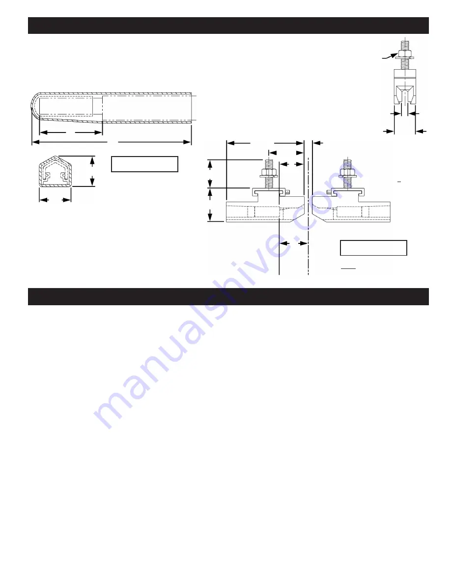
2.7 End Cap (See Figure 13)
2.7.1 If conductor bar has crimp splice, cut off splice and install
end cap.
2.8 Transfer Cap (See Figure 14)
2.8.1 Cut conductor bar 1” shorter than center
location of transfer cap. Prepare the end of the cluster
bar and cover in the same manner as one having a
splice installation.
2.8.2 Press transfer cap on cluster bar.
Figure 13
1”
3”
5/8”
5/8”
2.9 Collector Mounting Dimensions
(See Page 10)
3.0 Maintenance
3.1 Warning: Be sure power is turned off.
3.2 Maintenance of conductor system is dependent on atmospheric conditions and frequency of use. The frequency of inspection depends on the
age of the system. A new system should be checked after one month and again the following month until a pattern of maintenance is established. For
example, a class “C” (moderate service) crane handling 50% of rated capacity with 5 to 10 lifts per hour should require maintenance approximately
every six months after the first year of service.
3.3 Collectors
3.3.1 Any accumulation of dirt or dust should be removed from the collector.
3.3.2 Replace worn collector shoes.
3.3.3 Check spring tension to provide proper pressure on every collector shoe. Replace weak springs.
3.3.4
Note: Check for free mechanical action of collector to conductor. Clean and lubricate where necessary.
3.3.5 Realign collectors vertically and horizontally to the collector mount and to the conductor. Ensure that pigtail cable does not cause misalignment of
shoe on conductor.
3.4 Conductors
3.4.1 Wipe contact surface and cover clean of grease, dust and dirt. Sufficient accumulation may cause a ground.
3.4.2
Check straightness and alignment of conductor and relieving hanger clamps to permit sliding action for free expansion of conductor.
3.4.3 Check plastic cover for wear and misalignment at joints. Replace unduly worn sections. Check vertical and horizontal alignment of conductor.
3.4.4 Check at switches, transfer points, expansion gaps, etc., for wear. Replace unduly worn parts. Tighten loose bolts.
3.4.5 Where bar has been bent or joints broken by ladders, ropes, etc., or where bar has been pitted by arcing collector, replace by cutting out with
hacksaw and clamping new section in place.
1/4-20
.20”
3/4”
Misalignment
+1/8”
Содержание Cluster Bar
Страница 1: ...IOM CLUSTER BAR MANUAL 964000 5 0 1 Conductor Bar Manual Cluster Bar...
Страница 12: ...12 IOM CLUSTER BAR MANUAL 964000 5 0 5 0 Typical Installations...
Страница 13: ...13 IOM CLUSTER BAR MANUAL 964000 5 0 Notes...
Страница 14: ...14 IOM CLUSTER BAR MANUAL 964000 5 0 Notes...
Страница 15: ...15 IOM CLUSTER BAR MANUAL 964000 5 0 Notes...


