


the inner ends of the carbon tubes inside the fuselage (using a fine-toothed razor saw) to leave
a 52mm (2”) wide space between them. This is the width of the metal canard arm, plus the thick-
ness of 2 of the 6mm I.D. nylon washers supplied. (see photo P34 and 35)
Check for smooth fit of the shafts again. Check that the roots of both canards clear the sides of
the fuselage with about 25mm up and down movement, and adjust with extra plastic washers if
needed. Leave a gap of 0.75 - 1mm between the roots of the Canards and the fuselage.
Fit both canards with a plastic washer against the inner (cut) ends of the carbon tube, and join
with the machined metal canard arm provided. The control arm should be on the left side of the
fuselage, pointing upwards and angled about 25 - 30° degrees backwards from the vertical posi-
tion - towards the tail of the plane. Secure the carbon shafts by tightening the 4 small M3 bolts.
The ‘neutral’ position of the canards is when the roots align with the moulded ‘eyebrow’ profile
on the fuselage sides. (see photo P36)
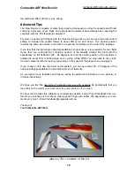
The canard servo can be fitted on the left side of the fuse-
lage, making sure that the servo output arm aligns with the
ball-link on the canard arm. We have included a milled ply-
wood servo mount for this, which can be glued against the
side of the fuselage and the top of the plywood ‘lattice’ rail.
Use the 10 x 10 x 70mm balsa block, glued onto the bottom
of the ply mount and sanded to the fuselage shape to get a
good gluing area. (see photo right)
Servo choice:
We recommend that you use a high quality servo of
at least
8kg torque for con-
trolling the canards, for example the digital JR8411 shown in the photos. It is also wise to fit
heavy-duty (or metal) servo output arm, as shown. At neutral the servo arm should angle back-
wards at approx. the same angle as the canard arm (25 - 30 degrees).
Note:
If using the canards as a ’speedbrake’ you will need to adjust these angles for the ‘neu-
tral’ position, and use a longer servo arm to obtain the larger throws needed.
Make up the linkage using the M3 all-thread rod supplied with the M3 steel clevis (and M3 nut)
to connect it to the servo arm, and the single M3 ball-link bolted to the inner side of the canard
control arm, with the M3 x 16mm bolt and locknut provided. Put one M3 washer on top of the
ball-link (under the head of the bolt) to make sure that the ball-link cannot come off in flight.
The hole in the bulkhead that supports the canard shaft tubes, and the nosegear mount, is large
enough to insert medium sized air tanks through if you should need, but if necessary you can
enlarge it a little at the top and bottom. With the longer nose of the ‘New Rookie’ you should not
need to position Nicads etc in the nose, even if you have a heavier turbine at the higher end of
the thrust range.
For the 1st flights, we strongly recommend that you restrict the canard throws to 15 - 20mm trail-
ing edge ‘down’ (mixed with ‘up’ elevator), and 10 - 15 mm trailing edge ‘up’ (mixed with ‘down’
elevator), until you are experienced with the very powerful effects on the flying characteristics of
the plane. If you chose to use combined Canards and Vector thrust at high speeds we recom-
mend you use a ‘low rate’ of canard throw.
Composite-ARF New Rookie
14