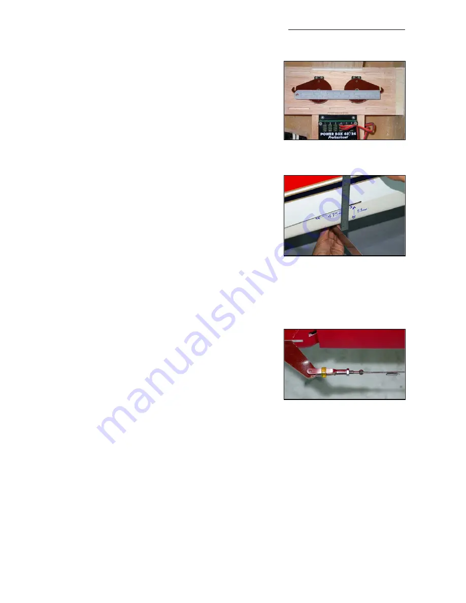
discs, and centre both servos using your R/C. Rough sand
and clean the bottom surface of the 2 phenolic horns, and
the top of the metal discs.
With the R/C still switched ‘ON’ place the C-ARF rudder
servo horns on top of the output discs, with both ‘hooks’
facing forwards, and align them exactly using a steel ruler
as shown in the photo above. Make sure that the back of
the hook slots and the output disc securing screws are all
perfectly in line. Tack glue the phenolic arms on top of the
output discs with a couple of drops of thick CA. When the
glue has cured, remove the arms and discs, drill through
both and secure with at least 2 small bolts, washers, lock-
nuts and Loctite (M2, 2/56 or equivalent). Finally add a drop
of Loctite to the bolts that secure the discs to the servos.
Make up the linkages between the servos from the M3 ball-
links and threaded rod included, as shown. Secure
just one
of the linkages between the phenolic arms, with the M3 x
16 bolts through the milled holes, with lock-nuts under-
neath. Adjust the length of the linkage very carefully until so
that there is minimal buzzing or humming from the servos
at idle, or at full throw. When satisfied, add the other link-
age and follow the same method of adjustment. (photo P9)
After the motor and exhaust system is finished, glue the
competed tank base/rudder servo tray into the fuselage
with 30 minute epoxy and micro-balloons mixture. Make
sure to get a good glue joint between the supports on the
bottom of the tank base and the wing tube sleeve. Install
the wings on the fuselage during this operation, to make
sure you cannot deform the fuselage. Scuff up the fuselage
where the parts will be glued in, and reinforce these impor-
tant joints with short lengths of the 1” fibreglass tape sup-
plied, using laminating epoxy. (photo P10)
With the rudder servos fitted in the recommended position,
then the centre of the slots that you must cut for the parallel pull-pull cables to the rudder is
475mm (18 3/4”) forward of the back edge of vertical fin, and 53mm (2 1/8“) up from the bottom
of the fuselage. Cut out a small slot first with a very sharp knife, check the position using the pull-
pull wire, and then adjust and open up the slots with a small file as needed. The slots need to be
about 3mm high and 50mm long. If you prefer to ‘cross’ your rudder cables, then these slots
should be 175mm forward of the fin TE, and approx. 33mm above the bottom of the fuselage.
Make the pull-pull wires from the hardware supplied, with a loop at the front that goes over the
hooks on the output arms, and a quick-link with threaded extender (turnbuckle) and locknut at
the rudder end. Pass the closed loop cable through the supplied ‘crimping tubes’ 2 times before
squashing flat with pliers (see photo). Make sure that the wires are tight, and check and adjust
after the first few flights as the cables straighten out. Even a small amount of slop will prevent
your Extra from perfect tracking. You can glue a very small scrap of ply or balsa across the front
of the slots on the servo arms with a drop of CA to prevent the wires coming out of the slots acci-
dentally.
Composite-ARF Extra 300SX
(2.6m span)
20
(above) Centre the servos with
your TX & align the horns very care-
fully with a steel straight edge.
(above) Slot positions for parallel
rudder cables.
(below) Pass rudder cable thru’
crimping tubes 2 times for safety,
and prevent all clevises from open-
ing with small pieces of tubing.


