Chapter 1: Introduction 1-3
Hardware Description
≥≥
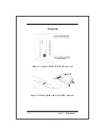
PCMCIA card
The Compex LinkPort PCMCIA Ethernet card’s main
PCB board is encased in a stainless compact frame. It has
a 68-pin connector that fits into a PCMCIA socket,. and a
15-pin flat connector that connects to the media coupler.
≥≥
Media Coupler
Media coupler incorporates RJ-45 10Base-T UTP
connector and BNC 10Base-2 coaxial connector.
≥≥
LED Indicators
↵
ACT LED (Colour: orange) Function: Monitors
signals transmitted to and received from the
network.
The orange LED, labelled ACT, lights up to
indicate that the PCMCIA Card is transmitting
signals to and/or receiving signals from the
network. This LED is normally OFF. It will flash
when the card transmits signals to the network.
The speed at which the LED flashes increases with
the level of network traffic.
↵
LINK LED (Colour: green) Function: Monitors
link status of twisted-pair connection. The
PCMCIA Card supports the link integrity test
function. This function is automatically enabled
when the card is configured for RJ-45 UTP cabling.
The green LED, labelled LINK, lights up to
indicate that a valid 10Base-T link has been
established. It is ON under normal operating
conditions. If the LED is OFF, check the RJ-45
port’s cable connection.
Note: The LINK LED only monitors the 10Base-T
(R J-45) connection. To check the condition of the
BNC link, run the diagnostics program.
Содержание LinkPort ENET-B
Страница 1: ...Compex LinkPort PCMCIA Ethernet Card ENET B User s Manual Version 1 7C...
Страница 7: ...vi NOTES...
Страница 19: ...3 4 Chapter 3 Installing the Drivers NOTES...
Страница 21: ...A 2 Appendix A Technical Information NOTES...
Страница 25: ...B 4 Appendix B Technical Support NOTES...
Страница 26: ...Appendix B Technical Support B 5 NOTES...
Страница 28: ...B 6 Appendix B Technical Support NOTES...


