6.
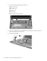
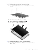
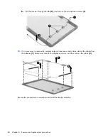
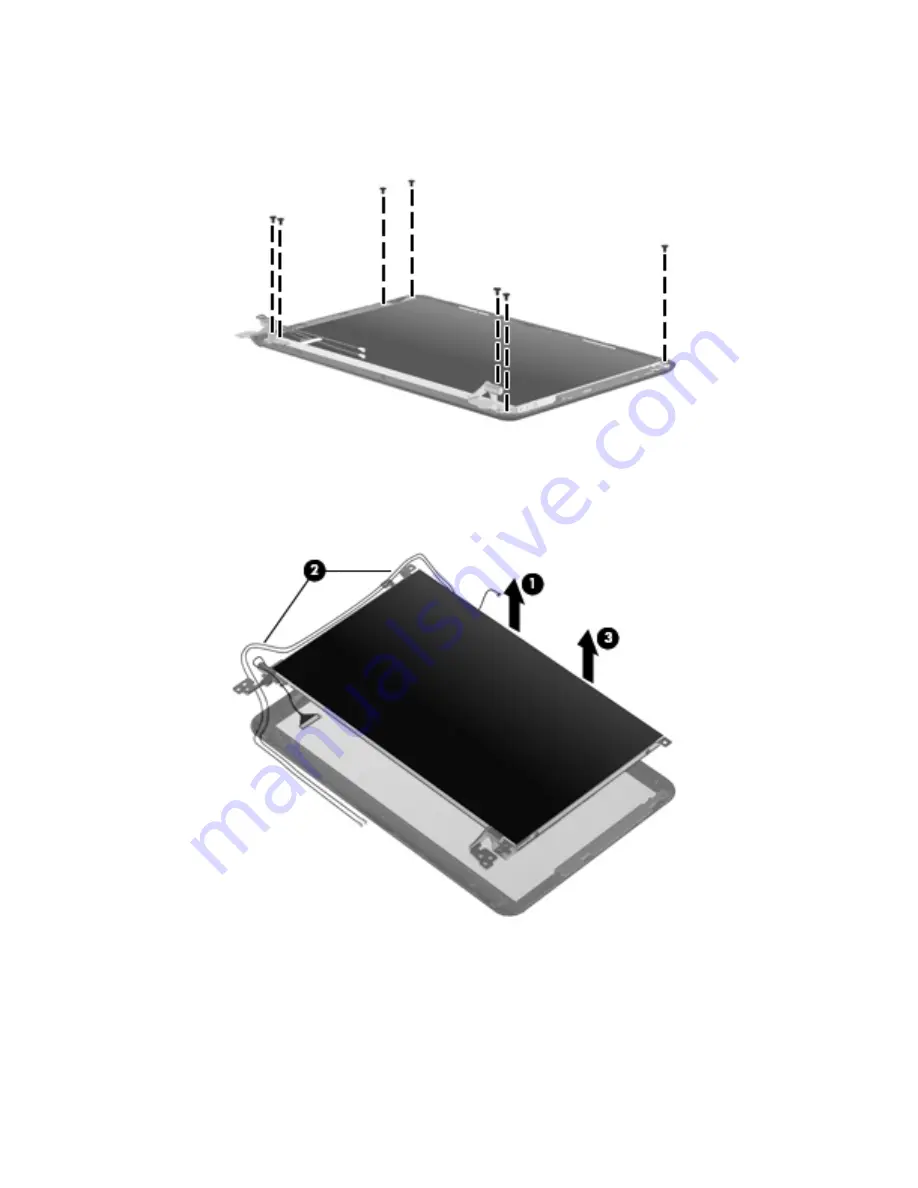
If it is necessary to replace the display panel, perform the following steps:
a.
Remove the 7 Phillips PM2.0×3.0 screws that secure the display panel to the display
enclosure.
b.
Lift the display panel up from the display enclosure
(1)
.
c.
Disconnect the webcam cable
(2)
from the system board
(2)
d.
Remove the display panel
(3)
from the display enclosure.
7.
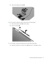
If it is necessary to replace the speaker assembly, perform the following steps:
a.
Remove the two Phillips PM2.0×3.0 screws
(1)
that secure the speaker assembly to the
display enclosure.
Component replacement procedures 65
Содержание Mini CQ10
Страница 1: ...Compaq Mini CQ10 Notebook PC Maintenance and Service Guide ...
Страница 4: ...iv Safety Warning Notice ...
Страница 8: ...viii ...
Страница 14: ...Light Component Description Caps lock light On Caps lock is on 6 Chapter 2 External component identification ...
Страница 64: ...3 Remove the fan 3 Reverse this procedure to install the fan 56 Chapter 4 Removal and replacement procedures ...
Страница 96: ...Universal Serial Bus Pin Signal 1 5 VDC 2 Data 3 Data 4 Ground 88 Chapter 8 Connector pin assignments ...

