Installation, Operating & Maintenance instructions
PAGE 7
Assembly
6
General
Before performing assembly, clean the grease in the cylinders
and all the actuator parts. Check the cylinder for any scratches.
The surface should be smooth and without any damage,
debris, rust or other contaminants.
Apply grease to all the parts prior to assembly.
6.1
If you have removed the pads, push them back into
their holes as shown in section 4.4.
6.2
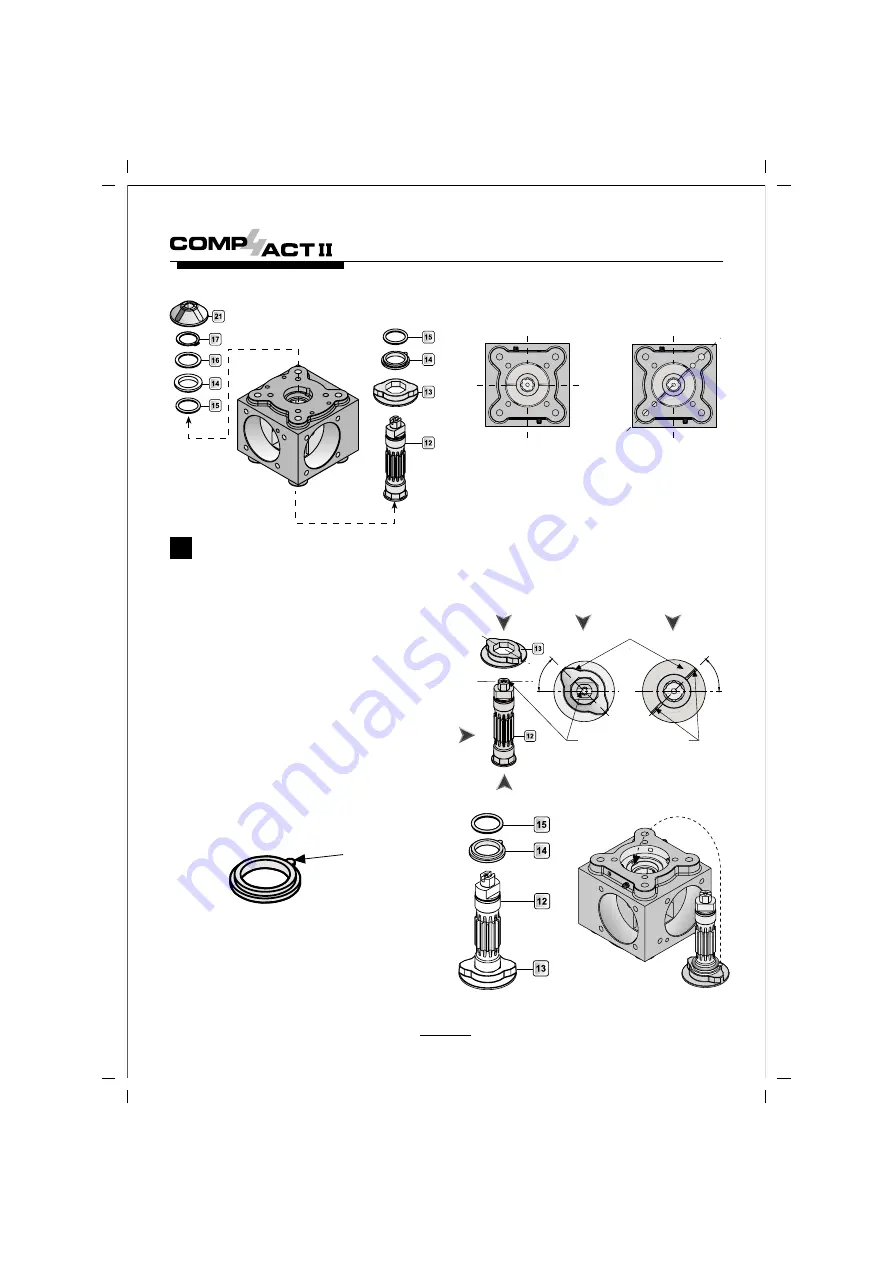
If the stop (13) has been removed from the pinion
(12), insert it back making sure the orientation of the
two stop protrusions are at 45
°
to the Namur slot as
shown in the drawing to the right. Use the two grooves
which are cast on the stop bottom plane to identify
the stop orientation.
6.3
Fit the thrust washer (14) and pinion O-ring (15) to the
pinion (12) and stop (13).
For C45 to C75 go to section 8.0
6.4
Insert the pinion assembly into the body. Make sure
that the thrust washer tongue engages to the opposing
groove in the body.
Thrust washer
tongue
6.5
When inserting the pinion to the body, bring the
grooves of the stop perpendicular to the adjustment
screws to ensure correct angle of rotation. Rotate the
pinion CCW until the protrusion flats hit the adjustment
screws and the grooves line up with the threaded
holes as shown below.
Step 1
Grooves perpendicular to
adjustment screws
Step 2
Grooves aligned to
adjustment screws
Bottom View
Bottom View
6.6 Fit the pinion O-ring (15), thrust washer (14) and disc
bearing (16) to the pinion. Make sure that the thrust
washer tongue engages to the opposing groove in
the body.
6.7
Always use a new circlip (17). Insert it on the pinion.
If the pinion does not protrude high enough, make
sure that the bottom thrust bearing tongue has properly
engaged into the body groove and the stop is recessed
in the body. Clip the indicator (21) back on the pinion.
6.8
Place the assembled body with the pinion on the rig
with the adaptor for inserting the pistons back in the
Position the Namur slot horizontaly and the stop protrusions
at 45
°
as shown. The stop has a groove that indicates the
orentation of the protrusions for ease of assembly.
Bottom View
Top View
45
°
45
°
Namur Slot
Stop
Protrusions
Grooves
Top View
Bottom View
Actuator bottom
plane
Trust washer
tongue engages
to groove in body


