INS_CNVETX1_REV– 06/10/13 PAGE 15
INSTALLATION AND OPERATION MANUAL
CNVETX1
TECH SUPPORT: 1.888.678.9427
Connecting the Cables
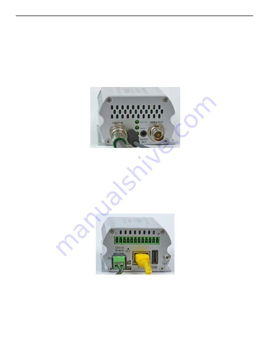
For viewing video, the video cable, Ethernet cable and power cable must be connected. Figure 5
below shows the front panel of the CNVETX1 configured as an Encoder with the BNC video input
cable and the audio input cable. In Decoder operation, the BNC video output and audio output
shall be used.
1. Connect the CNVETX1 video input using a standard 75Ω coaxial video cable.
2. Connect the audio input using standard 3.5 mm audio cable.
Figure 5: CNVETX1 Front Panel Connectors
Figure 6 and Figure 7 show the rear panel of the CNVETX1 with the RJ45 Ethernet connector,
power connector, terminal block mating connector for the alarms and relays, and USB connector.
3. Connect the CNVETX1 unit to the network using a standard network cable.
4. Connect the power using connector to the external DC power supply. If a PoE switch is used,
the network cable supplies the power to the unit.
5. Connect the alarms and TTL inputs via the terminal connector.
Figure 6: CNVETX1 Rear Panel Connectors


