


507868-02P
Page 13 of 48
Issue 1922
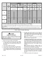
Table 4.
Piping and Fittings Specifications
Schedule 40 PVC (Pipe)
D1785
Schedule 40 PVC (Cellular Core Pipe)
F891
Schedule 40 PVC (Fittings)
D2466
Schedule 40 CPVC (Pipe)
F441
Schedule 40 CPVC (Fittings)
F438
SDR-21 PVC or SDR-26 PVC (Pipe)
D2241
SDR-21 CPVC or SDR-26 CPVC (Pipe)
F442
Schedule 40 ABS Cellular Core DWV
(Pipe)
F628
Schedule 40 ABS (Pipe)
D1527
Schedule 40 ABS (Fittings)
D2468
ABS-DWV (Drain Waste & Vent)
(Pipe & Fittings)
D2661
PVC-DWV (Drain Waste & Vent)
Pipe & Fittings)
D2665
PRIMER & SOLVENT CEMENT
ASTM
SPECIFICATION
PVC & CPVC Primer
F656
PVC Solvent Cement
D2564
CPVC Solvent Cement
F493
ABS Solvent Cement
D2235
PVC/CPVC/ABS All Purpose Cement For
Fittings & Pipe of the same material
D2564, D2235,
F493
ABS to PVC or CPVC Transition Solvent
Cement
D3138
CANADA PIPE & FITTING & SOLVENT
CEMENT
MARKING
PVC & CPVC Pipe and Fittings
ULCS636
PVC & CPVC Solvent Cement
ABS to PVC or CPVC Transition Cement
POLYPROPYLENE VENTING SYSTEM
ULC-S636
PolyPro® by Duravent
InnoFlue® by Centrotherm
ULC-S636
ECCO Polypropylene Vent
TM
ULC-S636
Pipe & Fittings Specifications
All pipe, fittings, primer and solvent cement must conform
with American National Standard Institute and the American
Society for Testing and Materials (ANSI/ASTM) standards.
The solvent shall be free flowing and contain no lumps,
undissolved particles or any foreign matter that adversely
affects the joint strength or chemical resistance of the
cement. The cement shall show no gelation, stratification,
or separation that cannot be removed by stirring. Refer to
Table 4 for approved piping and fitting materials.
Solvent cements for plastic pipe are flammable liquids
and should be kept away from all sources of ignition.
Do not use excessive amounts of solvent cement when
making joints. Good ventilation should be maintained to
reduce fire hazard and to minimize breathing of solvent
vapors. Avoid contact of cement with skin and eyes.
CAUTION
The exhaust and intake connections are made of PVC.
Use PVC primer and solvent cement when using PVC
vent pipe. When using ABS vent pipe, use transitional
solvent cement to make connections to the PVC fitting
in the unit.
IMPORTANT
Use PVC primer and solvent cement or ABS solvent
cement meeting ASTM specifications, refer to Table 4.
As an alternate, use all purpose cement, to bond ABS,
PVC, or CPVC pipe when using fittings and pipe made of
the same materials. Use transition solvent cement when
bonding ABS to either PVC or CPVC.
Low temperature solvent cement is recommended during
cooler weather. Metal or plastic strapping may be used as
vent pipe hangers. Uniformly apply a liberal coat of PVC
primer for PVC or use a clean dry cloth for ABS to clean
inside socket surface of fitting and male end of pipe to
depth of fitting socket.
Canadian Applications Only
Pipe, fittings, primer and solvent cement used to vent
(exhaust) this appliance must be certified to ULC S636 and
supplied by a single manufacturer as part of an approved
vent (exhaust) system. When bonding the vent system to
the furnace, use ULC S636 approved One-Step Transition
Cement to bond the pipe to the flue collar. In addition, the
first three feet of vent pipe from the furnace flue collar must
be accessible for inspection.
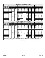
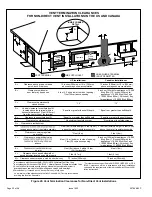
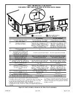
Table 5 lists the available exhaust termination kits. All vent
terminations are PVC.
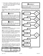
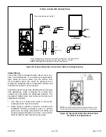
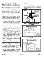
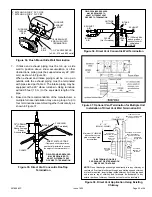
Joint Cementing Procedure
All cementing of joints should be done according to the
specifications outlined in ASTM D 2855.
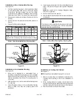
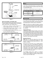
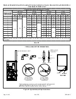
NOTE:
A sheet metal screw may be used to secure the
intake pipe to the connector, if desired. Use a drill or self
tapping screw to make a pilot hole.


