IMI
Installation
CHAPTER 2
INSTALLATION
CONSIDERATIONS
KSU and power supply cabinets should
be
attached vertically to
any sturdy, flat, surface.
They may be vertically rack mounted if
desired.
The power supply cabinet
can be mounted so that the power
connector and fuses are facing either toward the right side or
toward the left side of the mounting location.
power interconnection cable
is four feet in length.
Locate the
cabinets with respect to each other so that this cable will reach
between the cabinet connectors.
Do not locate the cabinets closer
than within six inches of each other.
power supply
must be
located within
six (6) feet of a proper
electrical outlet.
The power supply requires a dedicated
15
AMP circuit,
with a third-wire ground,
supplied to a
electrical outlet.
l
The distance between the
and the
jacks must be 25
feet
or less as per FCC requirements.
A nominal distance of 7 feet is
recommended.
mounting location
must be
secure and dry
a d e u a t e
ventilation.
The temperature range of the location must
e within
degrees F
degrees C),
and the relative
humidity must be
less than
percent non-condensing.
the mounting surface is
or if it is concrete or masonry
material, a backboard must
be
attached to the mounting surface to be
used for
KSU
mounting.
Suitable mounting backboards are
available
commercially or can be constructed
out
of
plywood cut to
size.
Tools and hardware required for mounting the KSU cabinet include:
@Fasteners
wood screws
x l-inch round head), toggle
bolts,
or wall anchors
*Screwdriver
to match fasteners
@Electric drill
if prepared holes are required
tool
for fastening wires to a type-66 connector
b l o c k .
@Crimping tool
for 623-type modular plugs
1.
Unpack,
and carefully inspect the
power supply, and stations
for shipping damage.
Notify the shipper immediately of any
damages found.
Verify that the packages contain all parts and
accessories needed for proper installation and operation.
2 .
If a backboard is required at the mounting location, attach it
securely to provide
a stable
mounting surface for the equipment.
2-l
Содержание Executech 2232
Страница 2: ......
Страница 3: ......
Страница 4: ......
Страница 5: ......
Страница 6: ......
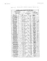
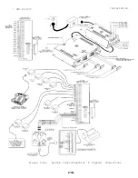
Страница 25: ... IMI 66 047 Installation L Figure 2 4a System Interconnection Typical Connections 2 15a ...
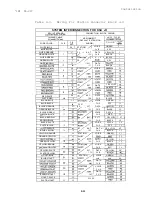
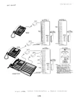
Страница 26: ...IN1 66 047 Installation 2 Figure 2 4b System Interconnection Typical Connections 2 15b ...
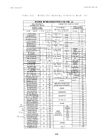
Страница 27: ...IMI 66 047 Installation 2 16 ...
Страница 28: ......
Страница 61: ......
Страница 71: ......
Страница 75: ......
Страница 79: ...COMDIAL Charlottesville Va 22901 PRINTED IN U S A 716604 700 01 ...
Страница 80: ......


