66-083
SECTION 6
SYSTEM CHECKOUT AND FAILURE ISOLATION
INITIAL CONDITION
GENERAL CHECK
The system operating features are set to
conditions at initial power-up. These conditions
provide a basic operating system with a known set of
parameters, and the system should be initially
checked out with the default conditions in place. At
any time while the system is operating, default
conditions can be reset from station port 10 or 12 per
the instructions provided in Chapter 4, Programming.
CHECK OUT
Check the common equipment and telephone
installation for proper operation by performing the
following resistance and voltage measurements.
1.
2.
3 .
Check the red light emitting diode (LED) system
status indicator. Be sure that it is on steady. If
is
off or flashing, refer to the paragraph below titled,
Failure Isolation.
Refer to Chapter 5 for operating information and
perform a general operational test of the system by
exercising the features from station port 10 or 11.
Operational parameters are per the system default
conditions as detailed in Chapter 4 until class of
service programming is performed.
Once the basic system is verified as operational,
perform the class of service programming as
described in Chapter 4.
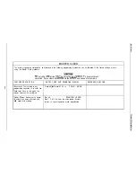
RESISTANCE CHECK
Measure the resistance at the station connector blocks
under the following conditions.
FAILURE ISOLATION
SYSTEM STATUS INDICATOR
AC power cord disconnected from electrical outlet.
Common equipment connected to station connector
blocks.
Stations wired and wiring punched down on blocks.
Bridging clips removed from blocks to isolate
stations from common equipment.
Measure the resistance of each installed station and
wiring from the station side of the connector blocks.
Resistance values will vary with cable length and
station type but should be within the following limits:
Greater than 700 Kohms
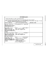
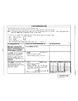
VOLTAGE CHECK
Make the following voltage measurements at the
station connector blocks under the following conditions:
l
Bridging clips installed
l
AC power connected to the common equipment
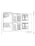
Measure the voltage across the signal pair. The
measured voltage must be within the following limits:
A red LED located on the common equipment cabinet
near the music port is the system status indicator.
This indicator is turned on steady when power is
applied to the system.
If the indicator flashes after
power up, it could be indicating a processor failure.
Unplug and reconnect the AC power to the power
supply and observe the LED indication. If it still shows
a flashing indication, equipment replacement may be
necessary.
STATION SELF TEST
The multiline stations can be self tested for proper
operation per the following instructions:
1.
2 .
3 .
Disconnect line cord at station base.
Press and hold MUTE and reconnect line cord to
station connector. Station will automatically
perform self test routine.
Release MUTE as soon as test begins. Sequence
of test is as follows:
l
Indicators will light in sequence
l
Ringer will sound be sure volume is set to low
or high
l
Indicators and ringer will then turn off at the
same time
4. Replace any station that does not pass the
test.
Содержание DIGITECH
Страница 13: ...System Overview l 6 ...
Страница 14: ..._ d33 System Overview J 0 I r0 0 0 t 0 0 0 0 0 0 0 0 0 l 7 ...
Страница 41: ...IMI 66 083 Table 3 2 J l Statlon Connections 4 Line Station Base Unit SPARE PORTS ...
Страница 46: ...Figure 3 4 Typical Llne Connections TO AUXILIMY JMH 4 TO AUXILIMY JAM 2 AK TIP I TIP 2 WfKJi 3 TIP 3 TIP 4 ...
Страница 47: ...IMI 66 083 Installat ...
Страница 55: ...IMI66 083 Installat llllllilliiiiiliiiil5 TTTTTTITTTTTTTTTTTTT 1111111111111111111 E 3 21 ...
Страница 62: ...installation IMI 66 083 Figure 3 16 Software Cartridge lnstallatlon and Removal 3 28 ...
Страница 106: ...System hogramming IMI 66 083 STATION LINECONFIGURATIONRECORD ...
Страница 110: ......
Страница 111: ......
Страница 112: ......
Страница 113: ......
Страница 137: ...LAST RESORT TABLE I U L COST T U 1 31TME 1 RATE q 2 RATF ICHARGE R2RATF 1 1 SURCHARGE 1 I ...
Страница 138: ...COST TABLE 20 I SURCHARGE I 2 RATF SURCHARGE ...
Страница 146: ...SYSTEM SPEED DIAL RECORD ...
Страница 181: ...Sjlstem Gperation IMI 66 083 ...
Страница 186: ...IMI 66 083 System OpeWion 1 1 5 27 ...


