


66-083
. . .
DATA DEVICE CONNECTIONS
‘The
provides two RS232 Data Ports for use.
l
When a video display terminal
is used
perform class of service programming, connect it
to
RS232 Data Port A.
l
When a serial data printer is used for SMDR,
SMDA, and
printout, connect it to the RS232
Data Port B.
The distance between the data device and the
common equipment can be up to 500 feet in a quiet
electrical environment. Shielded cable may be
required at some sites for long runs. For longer
distances, a limited distance modem must be used to
relay the data communications between the common
equipment and the data device.
When preparing a cable for connection to a data
device, refer to the manufacturer’s manual for the
equipment being interfaced and make the following
wiring connections:
Wire the common equipment RD (data from device
to common equipment) connection to the device TD
(transmit data) connection.
Wire the common equipment TD (data to device
from common equipment) connection to the device
RD (receive data) connection.
Wire the common equipment SG (signal ground)
connection to the device SG (signal ground)
connection.
If required for proper operation, wire the common
equipment CTS (clear-to-send status from device to
common equipment) connection to the device RTS
(request-to-send) connection.
NOTE: The common equipment requires a positive
voltage,
respect to signal ground, in order
send data.
The default data format is as follows. Configure the
data device to match this data format for initial
operation.
7-bit data with 2 stop bits and no parity
Baud rate of 300 baud
The Data Ports are located as follows and are
connected as illustrated in
Figure 3-12
on the next
&Station And
Base Units
Clip terminals 37 40 (data port A) and 41 44
(data
B) on station connector block.
SIG.
PORT A
PORT B
TERMINAL 37
TERMINAL 41
TERMINAL 38
TERMINAL 42
CTS =
TERMINAL 39
TERMINAL 43
SG=
TERMINAL 40
TERMINAL 44
Base Unit
Special modular jacks are available as data ports
SIG
JACK CONN.
None
1
CTS 2
RD 3
TD 4
SG
5
None 6
Содержание DIGITECH
Страница 13: ...System Overview l 6 ...
Страница 14: ..._ d33 System Overview J 0 I r0 0 0 t 0 0 0 0 0 0 0 0 0 l 7 ...
Страница 41: ...IMI 66 083 Table 3 2 J l Statlon Connections 4 Line Station Base Unit SPARE PORTS ...
Страница 46: ...Figure 3 4 Typical Llne Connections TO AUXILIMY JMH 4 TO AUXILIMY JAM 2 AK TIP I TIP 2 WfKJi 3 TIP 3 TIP 4 ...
Страница 47: ...IMI 66 083 Installat ...
Страница 55: ...IMI66 083 Installat llllllilliiiiiliiiil5 TTTTTTITTTTTTTTTTTTT 1111111111111111111 E 3 21 ...
Страница 62: ...installation IMI 66 083 Figure 3 16 Software Cartridge lnstallatlon and Removal 3 28 ...
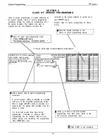
Страница 106: ...System hogramming IMI 66 083 STATION LINECONFIGURATIONRECORD ...
Страница 110: ......
Страница 111: ......
Страница 112: ......
Страница 113: ......
Страница 137: ...LAST RESORT TABLE I U L COST T U 1 31TME 1 RATE q 2 RATF ICHARGE R2RATF 1 1 SURCHARGE 1 I ...
Страница 138: ...COST TABLE 20 I SURCHARGE I 2 RATF SURCHARGE ...
Страница 146: ...SYSTEM SPEED DIAL RECORD ...
Страница 181: ...Sjlstem Gperation IMI 66 083 ...
Страница 186: ...IMI 66 083 System OpeWion 1 1 5 27 ...