


13
MACHINE PREPARATION
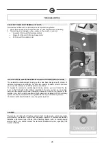
11. ADJUSTING THE HEIGHT OF THE SPLASH GUARD RUBBER SUPPORTS
During operation, the splash guard of the base must touch the floor lightly
To alter the height of the support, and therefore of the splash guard rubbers, tighten
or loosen the regulating knobs (1) so the rubber is parallel with the floor.
12. ASSEMBLING THE CYLINDRICAL BRUSHES
1. Connect the battery connector
2. Turn the key to position "1"
3. Move the lever to lift the base
4. Turn the key to position “0” and remove it from the electrical board
ATTENTION!
During this operation, check there are no people or
objects near the brush.
3
1
2
4
5. With the base up, release the clip (6) and unthread the front pin (5). Raise the
splash guard support (7) until the fixing screw (8) is in line with the hole.
6. Rotate the support (7), releasing it from the screw (8), and unthread the left-hand
splash guard.
7. To assemble the brush on the opposite side, repeat the same operations to
unthread the right-hand splash guard.
8.
To release the brush support plate (9), lower it until it touches the tunnel, then pull it
outwards.
9.
Insert the cylindrical brush (10) in the hole of the tunnel. Raise the brush, pushing it
forwards until its hub is inserted in the driving pulley.
10.
Insert the mobile pulley (11) - fixed to the brush support (9) - in the cylindrical brush
(10).
11.
Raise the support (9) and hook the teeth up to the tunnel shoulder. At the same time,
lower the hook-up lever (12) until it is inserted in the square hole on the support (9).
12.
Release the support (9) by pushing it slightly forwards until the end of its upward
stroke
13.
Repeat the same operations for the right-hand brush support
14.
Adjust the alignment of the brushes by means of the screw (13), so the lower edge of
the support (9) coincides with the end of the brushing tunnel.
15.
Reassemble the side splash guards, repeating the release operations in the reverse
order.
1
1
7
5
6
9
10
8
11
12
13