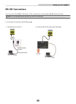
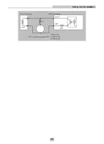


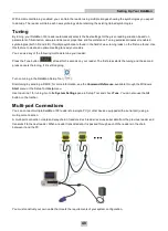
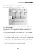


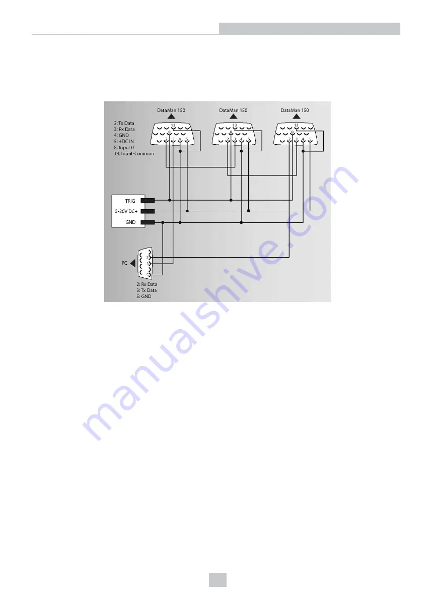
The cable must provide a DB-15 connector for each DataMan 150 and a DB-9 connector for the PC serial port. Each DB-
15 connector must provide Tx Data, Rx Data, Trigger (Input 0), ground, and DC power. The Tx Data and Rx Data pins on
adjacent connectors must be connected to provide the multi-port connection.
The following diagram shows how to create a multi-port cable for a 3-reader system. In the example, all the readers
share a common trigger. It is also possible to wire individual triggers for each reader.
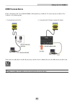
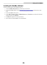
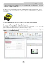
You must connect each DataMan 150 to DataMan Setup Tool using a USB connection and set the DataMan for multi-
port operation. To configure a DataMan 150 for multi-port operation, click on the
Enable Multi-Port (RS-232 Sharing)
check box in
Communication Settings
.
There is no guaranteed delivery order when multiple readers transmit data using a multi-port connection; read results
may arrive at the PC in any order. You can configure each DataMan 150 reader in a multi-port connection to add
identifying data to each read result. Your PC application can then determine which reader produced a specific read
result.
To do this, check the
Standard Formatting Enabled
box (for each symbology that you are using) in
Data Formatting
,
and enter text in the
Leading Text
field. (You can also add trailing text by entering text in the
Trailing Text
field.)
You can obtain the best results when using multi-port connections by keeping the following usage guidelines in mind as
you design your system:
l
The maximum cable length between any two DataMan 150 readers or between the PC and any DataMan reader
should be no greater than 15 meters.
l
There is no fixed limit to the number of DataMan 150 readers that you can connect to a single PC. Each reader
introduces a delay of about 100 ms when it retransmits received serial data. If you have 5 readers, this means
that there will be a 400 ms delay between the time the first reader in the chain transmits data and the PC receives
it.
l
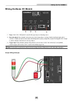
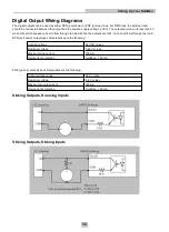
Each DataMan 150 reader must receive a hardware trigger signal on its Input 0 line. You can wire the input ports
to a common trigger signal or you can provide individual triggers for each reader.
41
Setting Up Your DataMan
Содержание DataMan 150
Страница 1: ...DataMan 150 Quick Reference Guide 4 24 2015 Version 5 5 0 ...
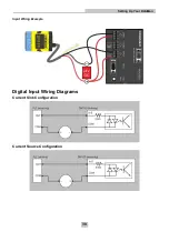
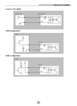
Страница 31: ...Load to a TTL Buffer PNP Configuration NPN Configutation 31 Setting Up Your DataMan ...
Страница 33: ...33 Setting Up Your DataMan ...
Страница 47: ......


