


External Devices
and Connections
Intro
Operation
Customer
Assistance
Warranty
Notice
Secondary Icons
Caution
Warning
Installation
Customer
Assistance
Installation and Start-Up
External Devices and Connections
•
Your CobraMarine
™
VHF radio is set up to connect auxiliary devices for navigation,
convenience and added versatility. As is the case with the antenna, choosing these
devices is best done with the advice and guidance of a knowledgeable dealer. Standard
connectors are provided on the front and back of the transceiver.
Microphone/Speaker Attachment
Connect the Microphone/Speaker to the cord socket located at the left side of
the front of the transceiver.
To connect the microphone/speaker attachment:
1. Align the connector and push it firmly into the socket.
2. Tighten the captive nut to hold the connector in place.
3. Slide the waterproof sleeve over the nut until it seats
in the recess around the socket.
External Speaker (not included)
An External Speaker can provide greater volume to hear messages
than the speaker incorporated in the CobraMarine
™
microphone/speaker.
To install an external speaker:
1. Connect the speaker lead to the
standard jack on the back of the
transceiver.
Public Address Speaker (Hailer) (not included)
At times, it may be handy to hail other boats or give instructions to line handlers
on the dock. Your CobraMarine
™
VHF radio can be switched to operate in the Public
Address mode through an attached PA speaker.
To install a public address speaker:
1. Connect the PA speaker lead to the standard
jack on the back of the transceiver.
NOTE
The External Speaker and PA Jack on the back of the
transceiver requires a 3.5 mm standard stereo plug that is
wired appropriately for either or both auxiliary speakers:
1. Tip of plug
External Speaker output
2. Ring Conductor
PA output
3. Sleeve
Ground
A single speaker cannot be used for the separate functions
of External Speaker and Public Address Speaker.
30 English
Nothing
comes close to a Cobra
®
31
Getting Started
Global Positioning System (GPS) Device (not included)
Cobra Electronics Corporation
™
strongly recommends that you obtain and connect
a GPS device to your CobraMarine
™
VHF radio. By having a GPS connected, your
position will be continuously indicated on the LCD and, most importantly, it will
be included automatically in any DSC distress message you may need to send.
That will take the “search” out of “search and rescue.”
To install a GPS device:
1. Install the GPS device in a convenient location
according to its manufacturer’s directions.
2. Bond the NMEA out negative wire to the black
wire of the GPS interface cable.
3. Bond the NMEA out positive wire to the red
wire of the GPS interface cable.
NOTE
When bonding the wires, make sure connections
are secure and properly insulated.
4. Connect the new combination cable to the GPS
device and to the back of the transceiver.
NOTE
Satellite acquisition time is dependent on the
GPS device.
Getting Started
•
Refer to the foldout on the front cover of this manual to identify the various
controls and indicators on your radio.
Throughout this manual you will be instructed to press or to press and hold buttons
on the transceiver or on the microphone/speaker. Press means a momentary press,
then release; press and hold means to hold the button down.
Tones and Alarms
When your CobraMarine
™
VHF radio is on, you can expect to hear the following
tones and alarms. The volume of these sounds is controlled by the circuitry in the
radio and is not affected by the volume set with the On-Off Power/Volume knob or
Volume Up/Down buttons.
Intro
Operation
Customer
Assistance
Warranty
Notice
Main Icons
Secondary Icons
Caution
Warning
Installation
Customer
Assistance
Intro
Operation
Customer
Assistance
Warranty
Notice
Secondary Icons
Caution
Warning
Installation
Customer
Assistance
Installation and Start-Up
Microphone/Speaker
Cord Connection Socket
Intro
Operation
Customer
Assistance
Warranty
Notice
Main Icons
Secondary Icons
Caution
Warning
Installation
Customer
Assistance
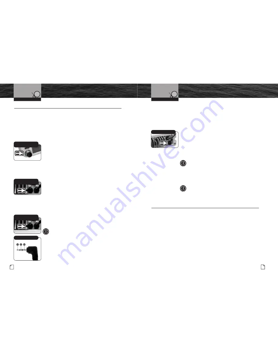
External Speaker and PA
Jack: See NOTE Below
Intro
Operation
Customer
Assistance
Warranty
Notice
Main Icons
Secondary Icons
Caution
Warning
Installation
Customer
Assistance
External Speaker and PA
Jack: See NOTE Below
GPS Connection
Intro
Operation
Customer
Assistance
Warranty
Notice
Main Icons
Secondary Icons
Caution
Warning
Installation
Customer
Assistance
Stereo Plug
Intro
Operation
Customer
Assistance
Warranty
Notice
Main Icons
Secondary Icons
Caution
Warning
Installation
Customer
Assistance
Intro
Operation
Customer
Assistance
Warranty
Notice
Main Icons
Secondary Icons
Caution
Warning
Installation
Customer
Assistance
Intro
Operation
Customer
Assistance
Warranty
Notice
Main Icons
Secondary Icons
Caution
Warning
Installation
Customer
Assistance
1 2 3


