Important: Always read and follow the on-screen operating instructions.
• 19
V
Viid
de
eo
o B
Ba
alla
an
nc
ce
er
r
M
Ma
an
nu
ua
alllly
y S
Se
et
tt
tiin
ng
g W
Wh
he
ee
ell
D
Diim
me
en
ns
siio
on
ns
s (
(D
DI
IM
M)
)
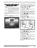
Definition of dimensions (DIM):
A = Offset
The distance measured from the bal-
ancer (“0” on the offset arm) to the inner
plane of the rim (inner weight location).
W = Width
The width of the wheel at the rim
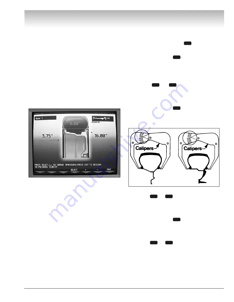
flanges, measured with the calipers as
shown in figure 32.
Note:
Only use calipers provided by the wheel bal-
ancer manufacturer because others may not be the
same.
D = Diameter
The diameter of the wheel as indi-
cated on the tire.
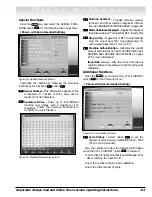
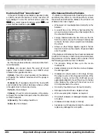
Figure 31 - Manual Measurements Screen
When necessary, the wheel dimensions can be
inserted or edited in manual mode. At the initial screen
or during calibrations follow these instructions on-
screen when setting DIM option
.
Manually Setting “A” DIM
1.
Press SELECT option
to highlight (in red) the
rim offset (A) DIM.
2.
Position offset arm at clip-on weight location on
wheel and read the number, on the slide out offset
arm, at the cabinet (this is the correct offset DIM).
3.
Using
+
or
-
, manually set the offset
DIM on-screen (highlighted red) to match the offset
number of the mounted tire.
Manually Setting “W” DIM
1.
Press SELECT option
to highlight (in red) the
rim width (W) DIM.
2.
Use the plastic calipers provided with the wheel
balancer to measure the wheel width.
Figure 32 - Caliper Location Diagrams
3.
Using
+
or
-
, manually set the rim width
DIM on-screen (highlighted red) to match the meas-
ured caliper width of the mounted rim.
Manually Setting “D” DIM
1.
Press SELECT option
to highlight (in red) the
rim diameter (D) DIM.
2.
Inspect mounted tire sidewall to determine the
exact diameter that is printed on the tire.
3.
Using
+
or
-
, manually set the tire diam-
eter DIM on-screen (highlighted red) to match the tire
sidewall size.
6
5
4
6
5
4
6
5
4
3
Steel Wheels
Alloy Wheels
W
A
D


