


bâàwÉÉÜ fÑxxw WÉÅx fxÜ|xá |Ñ@åÇxà
14
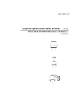
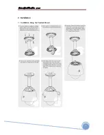
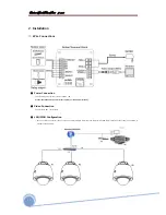
2. Installation
■ Sensor Input/Relay Output
• Sensor input connection
Before connecting sensors, check driving voltage and output signal type of the sensor.
Since output signal types of the sensors are divided into Open Collector and Voltage Output type in general, the cabling must be done properly after
considering these types.
Also, the sensor type, i.e. “Normal Open” or “Normal Close” in DIP switch in main body of camera must be set properly.
Signal Line
Description
IN COM+
C)cable of electric power source for sensors to this port as shown in the
circuit above.
IN1 -, IN2 -, IN3 -, In4 -
Connect output of sensors for each port as shown in the circuit above.
• Relay output connection
Maximum allowable electrical load of relay is shown bellow table.
Driving Power
DC
110VAC
220VAC
Max. Capacity
28VDC, 3A
110VAC, 3A
250VAC, 3A
Содержание IS2765N
Страница 10: ...b w f xxw W x fx x x 10 General LAN WAN Configuration...
Страница 11: ...b w f xxw W x fx x x 11 2 Installation Installation Using the Wall Mount...
Страница 12: ...b w f xxw W x fx x x 12 2 Installation Installation Using the Pendant Mount...
Страница 16: ...b w f xxw W x fx x x 16 Figure 3 1 Log in window...
Страница 46: ...b w f xxw W x fx x x 46 MEMO...
Страница 86: ...b w f xxw W x fx x x 86 MEMO...
Страница 89: ...b w f xxw W x fx x x 89 6 Specifications Dimensional Drawings unit mm...
Страница 90: ...b w f xxw W x fx x x 90 6 Specifications Dimensional Drawings Unit mm...
Страница 92: ...b w f xxw W x fx x x 92 MEMO...


