background image

 Automation Motor Mix Operations Manual v 2.0 2/00 Page 8

Standard Operations

Description of Controls and Displays

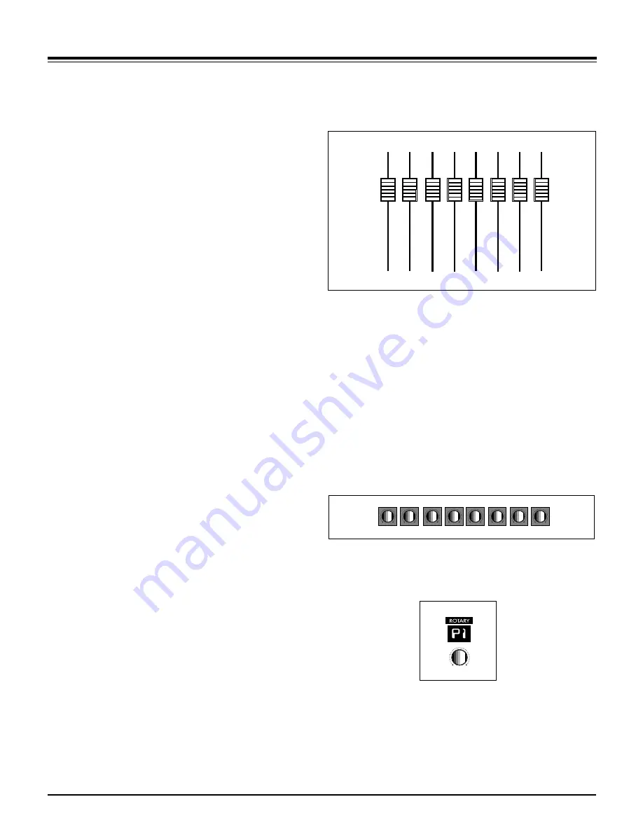
Fader Input

When the faders are not being moved by the computer, you can move
them. Motor Mix disengages the motor so you can make level changes.
The motor will stay disengaged as long as you continue to move the fader.
If you wish to keep the fader stationary but keep the motor disengaged,
press and hold the "SHIFT" switch. The motors will engage as soon as the
"SHIFT” switch is released. If you wish to make very small fader move-
ments quite slowly, press the “SHIFT” switch. This keeps the faders touch
released during the small fader movements.

Shift “double click”

Click the shift switch twice quickly and its LED will blink. It is like holding
the “SHIFT” switch down to hold faders punched in. Any fader that is
punched in will remain punched in until either the “SHIFT” switch or the
“write” shift is pressed. Press the “shift” switch twice quickly to exit. The
“SHIFT” switch still performs its normal functions while in this mode.

The yellow LED (funct B) below the “write” LED lites to show that one or
more faders are punched in. A punched in fader will send moves out and
the motor(s) will remain off. Press the “write” or “SHIFT” switch to punch
out all faders, and the LED will extinguish. If the transport is playing,
pressing “Stop”, “PLAY”, “FFWD” or “REW” will also punch out the faders.

If a fader is being moved by the computer, press a “burn” button to punch
the fader in and it will remain punched in regardless of the “SHIFT” switch.
The “funct B” LED lites to show that faders are also punched in. Press the
channel “burn” switch a second time to punch it out. Press the “write” or
“SHIFT” switch to punch out all faders, and the “funct B” LED will extin-
guish. If the transport is playing, pressing “Stop”, “PLAY”, “FFWD” or
“REW” will also punch out the faders.

Rotary Pots

The 8 rotary pots on Motor Mix send out relative information only, since
the application always knows the current setting. The bottom row of the
LCD indicates the current pot settings either graphically or numerically
depending on the application. The pots simply add or subtract to the
current setting. These pots are intended to control pan, aux send levels,
equalizers, and any plug-ins you may have installed.

Rotary Selector

Used in conjunction with the 7 segment display to select what the rotary
pots are controlling. Normally, the pots start out controlling pan. Rotating
this selector should cause the pots to change their task. Typically, they
would go from pan to aux1 to aux2 to aux3, etc. The 7 segment display
should give some indication of what the rotary pots are controlling:
P=(pan), A1=(aux1), A2=(aux2), etc. The utility of these controls depends
on how the host application has implemented them.

Содержание MotorMix

Страница 1: ...r s Manual Version 2 0 Before you call us with your questions please read the manual at least once This way we can improve the quality of our customer support and create better manuals The manual prov...

Страница 2: ...m you of all product updates as well as new product developments Some of these updates will be free so please send the card in CM Automation reserves the right to make improvements or changes at any t...

Страница 3: ...Pro Tools Operations Set Up Quickstart 1 Troubleshooting 2 Operation 3 6 Multi Unit Benefits 7 Standard Operations Set Up Troubleshooting 8 Operations 9 11 Multi Unit Benefits Standard Operations 12 M...

Страница 4: ...but create a unique name for each unit like Motor Mix 1 Motor Mix 2 etc 6 If you are using Pro Tools 5 xx pull down the MIDI menu and select MIDI Input Devices Click on each Motor Mix listed This will...

Страница 5: ...ms elsewhere Contacting Technical Support For questions related to setting up and using Motor Mix with Pro Tools or if you feel that Motor Mix needs to be repaired contact the Digidesign technical sup...

Страница 6: ...ots or Selector Usage with Pro Tools Fader Input Moving a fader on Motor Mix actually moves the Pro Tools on screen fader When Pro Tools Automation is moving the faders on Motor Mix you can still make...

Страница 7: ...gn switch again to complete assignments for that insert 6 Repeat steps 3 5 to add more plug ins to that channel PLUG IN Control Use the SELECT switch to select a channel with a Plug in assigned Press...

Страница 8: ...l be lit to indicate Pro Tools is in fast foreword monitor With SHIFT pressed down press the monitor switch The bottom row of the LCD will show 5 punch monitor controls and the current time code bars...

Страница 9: ...o Tools supports up to 4 Motor Mixes Each Motor Mix uses one MIDI IN OUT port When you have three Motor Mixes joined together and you bank switch the bank is 24 channels wide You can combine them in t...

Страница 10: ...tware support manual provided by the software company We will post software installation procedures on our web site cmautomation com as they become available Troubleshooting If Motor Mix does not resp...

Страница 11: ...will extinguish If the transport is playing pressing Stop PLAY FFWD or REW will also punch out the faders If a fader is being moved by the computer press a burn button to punch the fader in and it wi...

Страница 12: ...The LCD has only 5 characters per channel so use 5 characters or less when you create your channel names 2 With the BANK switch on you see channels 1 8 Press the right arrow and you advance immediatel...

Страница 13: ...te is engaged the red LED is lit Left and Right Function Switches These are the switches to the left and right of the faders on Motor Mix All 16 of these switches have a green LED The SHIFT switch at...

Страница 14: ...ustom console tailored to the way you work Some DAW software supports multiple Motor Mixes Each Motor Mix uses one MIDI IN OUT port You can combine them in two basic ways 1 In line configuaration 2 Sp...

Страница 15: ...face also needs to be light and mobile so it can be easily moved about the workspace 5 The worksurface must NOT limit the number of available channels even thought it only has eight faders The process...

Страница 16: ...els Motor Mix can be set to view individual channels banks of 8 channels or groups of up to 8 channels All by 2 simple key strokes 8 MUTE Switches with red LED status indicator 8 SOLO Switches with gr...

Страница 17: ...CM Automation Motor Mix Operations Manual v 2 0 2 00 Page 14 Worksurface Layout...

Страница 18: ...Page 15 CM Automation Motor Mix Operations Manual v 2 0 2 00 Back Panel Layout...

Отзывы: