CDI-46 Installation and Setup Guide V1.3
6
CDI-46 jumper settings
The CDI-46 has three PCB jumpers: J1, J2 and J3.
IMPORTANT: It should never be necessary to move any of the CDI-46’s jumpers under normal circumstances.
Installers are strongly advised to contact Cloud’s Technical Dept. at
in the event of a problem.
JUMPER
DESCRIPTION
EFFECT
DEFAULT
J1
PM microphone termination
ON: 46-120 is at end of network “chain”
OFF: Special circumstances only
ON
J2
Forces CDI-46 boot load
mode
OFF: Normal operation
ON: Special circumstances only
OFF
J3
Reset internal NVM memory
OFF: Normal operation
ON: Restores all factory default settings
OFF
Using the Digital Paging Interface
The CDI-46 is fitted with a Cloud Digital Paging Interface; this uses the
CDPM/PM INPUT RJ45 socket. When fitted, the
CDPM/PM interface uses the same signal path within the 46/120 as Mic 1, and therefore the front-panel
MIC 1 Level controls,
and rear-panel
MIC 1/TEL GAIN, LF
and
HF EQ controls should be adjusted to obtain the correct paging level in each zone.
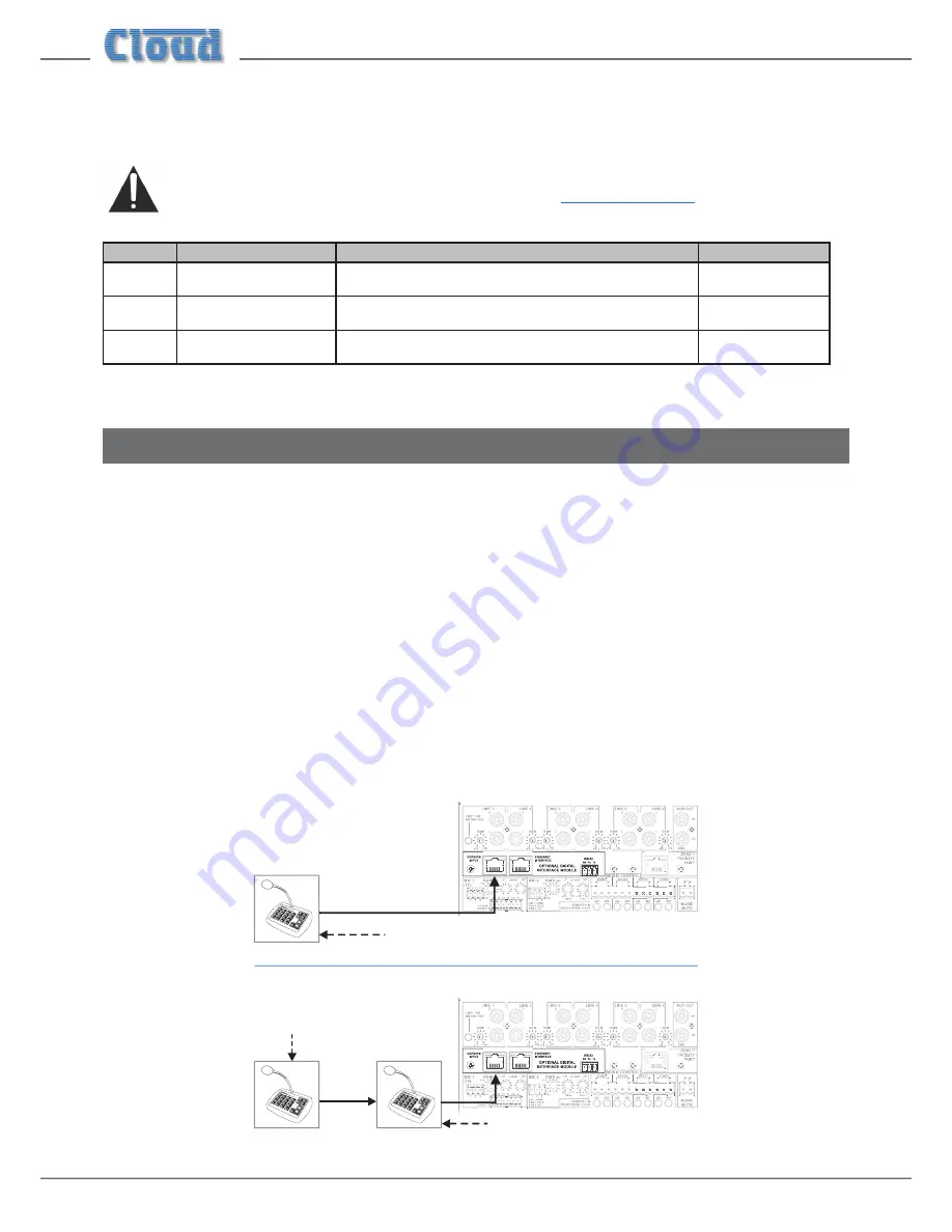
Cloud PM Series Paging microphones may be connected directly to the
CDPM/PM INPUT with Cat 5 cable; the single
connection provides all audio, control and power required by the microphone. (Note that this connector has no LEDs.)
The
CDPM/PM INPUT port is able to supply 250 mA* to power paging microphones. This is adequate to power one or
two microphones of models PM-4, PM-8 or PM-12. Cloud recommend that PM-16 microphones, and all ‘-SA’ models (with
spot announcement sound stores) are powered by a separate, external PSU, as described in the PM Series Installation Guide.
(A suitable PSU is supplied as standard with all ‘-SA’ models.)
As the 46-120 only supports four zones, it is likely that a PM-4 or PM-4SA will be the models most used. If multiple 46-120s are
in use to cover a larger number of zones, the analogue interfaces on the PM and the 46-120 should be used instead. Please refer
to the 46-120 Installation and User Guide for information regarding the use of the analogue interface.
Connect the
OUT socket of the PM Series microphone to the CDPM/PM INPUT socket of the CDI-46 with Cat 5 cable.
If more than one paging microphone is in use – typically at different locations in the building – the microphones should be “daisy-
chained”, with the
OUT socket of one being wired to the IN
socket of the next.
46-120
IN
OUT
OUT
46-120
OUT
Termination ON
Termination OFF
Termination
ON
* This figure should be reduced at elevated temperatures by approximately 3 mA/°C above 23°C.


