8
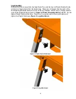
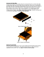
Figure 1: Head Locking Screw Removal
Figure 2: Head Locking Handle Installation
Depth Limiting Bolt:
Remove the 12mm Carriage Bolt, 12mm Large Flat Washer (DIN9021), 12mm Flat
Washer, 12mm Lock Washer, and 12mm Nut from the plastic Bag. Place the 12mm Large
Washer over the 12mm Carriage Bolt. Slide the 12mm Carriage thru the Head Locking
handle Slot either above the Head Locking Handle (to limit the depth of cut) or below the
Head Locking Handle (to limit the tilt angle of the Cutting Head) and attach the 12mm Flat
Washer, 12mm Lock Washer, and 12mm Nut as show in
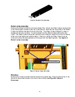
Figure 3: Depth Limiting Bolt
Assembly
.
Figure 3: Depth Limiting Bolt Assembly
Содержание BBC157
Страница 1: ...OWNERS MANUAL COMPACT MASONRY SAW MODELS BBC157 BBC207 BBC547 FORM 7506 rev 2 2006...
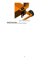
Страница 12: ...12 Figure 10 Wrench Placement Water Pump Assembly The Water Pump requires no additional assembly...
Страница 25: ...25 V PARTS LIST SECTION Power Plant BBC547 Gasoline S 1 S 2...
Страница 28: ...28 Frame Common All BBC157 207 547...
Страница 30: ...30 Cutting Head Common All BBC157 207 547...
Страница 32: ...32 Cutting Table Common All BBC157 207 547...
Страница 34: ...34 C Baldor Service Policy...
Страница 35: ...35 D Honda Service Policy...

