background image


1

3

R

R

e

e

m

m

o

o

t

t

e

e


K

K

e

e

y

y

p

p

a

a

d

d


(

(

K

K

P

P

-

-

1

1

5

5

/

/


K

K

P

P

A

A

-

-

1

1

5

5

)

)


2

2

1

1

-

-

D

D

E

E

C

C

-

-

2

2

0

0

0

0

9

9


z

z


I

I

d

d

e

e

n

n

t

t

i

i

f

f

y

y

i

i

n

n

g

g


t

t

h

h

e

e


P

P

a

a

r

r

t

t

s

s

:

:


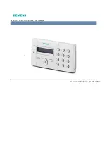
Green Active LED 

Red TX LED 

Orange Fault LED 

Slide Out Section 

Arm Key 

Home Key 

Χ

 Key 

Disarm Key 

 Key  

¿

 Key 

+ Key   

-press both 7 and 9 to trigger emergency alarm 

Fire Key   

-press both 4 and 6 to trigger fire alarm


A Key   

-press both 1 and 3 to trigger panic alarm


Mounting Hole 

Buzzer 

Battery Insulator

z

z


L

L

E

E

D

D


I

I

n

n

d

d

i

i

c

c

a

a

t

t

o

o

r

r

:

:


z

z


G

G

r

r

e

e

e

e

n

n


A

A

c

c

t

t

i

i

v

v

e

e


L

L

E

E

D

D

:

:


z


Green Active LED on: the system is in 

Normal Operation Mode

z


Green Active LED flash: the system is in 

Test Mode

.  

z


When the Keypad is idle, all LEDs are off. After any key press, the 

G

G

r

r

e

e

e

e

n

n Active LED turns on for 5 

seconds indicating that Keypad is active. 

z


T

T

h

h

e

e


G

G

r

r

e

e

e

e

n

n Active LED will turn off after successful completion of a valid keystroke sequence or 

when the pause in between key stokes is longer than 5 seconds. 

z

 When 

the 

G

G

r

r

e

e

e

e

n

n Active LED turns off before a valid keystroke sequence is completed (5 seconds), 

the previous entered keys are ignored. 

z

z


R

R

e

e

d

d


T

T

X

X


L

L

E

E

D

D

:

:


z


The Red TX LED flashes 2 times: the signal is transmitted. 

z

z


O

O

r

r

a

a

n

n

g

g

e

e


F

F

a

a

u

u

l

l

t

t


L

L

E

E

D

D

:

:


z


Orange Fault LED flashes for 5 times: Battery is low during operation.   

<

<

N

N

O

O

T

T

E

E

>

>


&

&


A short beep will be sounded with each key press, which confirms valid pressing. 


1


2

7

4

5

6

8

9


Содержание KP-15

Страница 1: ...e LED flash the system is in Test Mode z When the Keypad is idle all LEDs are off After any key press the G Gr re ee en n Active LED turns on for 5 seconds indicating that Keypad is active z T Th he e G Gr re ee en n Active LED will turn off after successful completion of a valid keystroke sequence or when the pause in between key stokes is longer than 5 seconds z When the G Gr re ee en n Active L...

Страница 2: ... T Te es st t m mo od de e z Keypad can be put into Test mode by entering the PIN code default 0000 followed by The Green Active LED will flash and Keypad sounds a long beep z To exit Test mode press twice Keypad will sound a long beep and the Green Active LED will turn on then Keypad returns to Normal Operation mode N NO OT TE E When Keypad is in Test mode it operates as wake up condition thus wi...

Страница 3: ...nting holes as a template mark off the positions in the most appropriate place III Insert the wall plugs if fixing into plaster or brick surface IV Screw the Keypad onto the wall plugs V Replace the 2 slide out sections z z H Ho ow w t to o S Se et t S Sy ys st te em m M Mo od de e Arm Home with Pin Code Arm Mode Enter anyone of Control Panel user codes and press key Red TX LED will flash 5 times ...

Страница 4: ...pen the Keypad by loosening the 2 fixing screw located behind the Keypad IV Take out the old battery and wait for 5 minutes before replacing the new battery in the battery compartment with unmarked negative side of battery facing down V Close the case using the rear fixing screws VI Screw back the Keypad to the surface with mounting screws and then re insert the slide outs VII Put the Control Pane...

Страница 5: ...If this equipment does cause harmful interference to radio or television reception which can be determined by turning the equipment off and on the user is encouraged to try to correct the interference by one of the following measures Reorient or relocate the receiving antenna Increase the separation between the equipment and receiver Connect the equipment into an outlet on a circuit different from...

Отзывы: