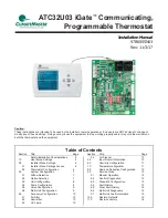


AT C 3 2 U 0 3 C o m m u n i c a t i n g , P ro g r a m m a b l e T h e r m o s t a t - I O M
R e v. : N o v e m b e r 3 , 2 0 1 7
8
G e o t h e r m a l H e a t P u m p S y s t e m s
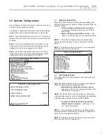
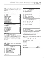
OPTION SELECTION
MOTORIZED VALVE OFF
COMPRESSOR ASCD 5
PREVIOUS NEXT
CAUTION!
CAUTION!
This is a Commercial option only and does not
alter Residential unit operation.
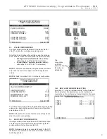
3.3 UNIT
CONFIGURATION
Adjust the Unit Confi guration settings including Heat
Pump Family, Heat Pump Size, Blower Type, and Loop
Confi guration using the up/down arrow buttons. Press the
center button to select each item.
• Heat Pump Family (default stored in control) –
valid range: TE, TY, TES, TEP, TRT, TSM
• Heat Pump Size (default stored in control) –
valid range: depends on Heat Pump Family setting
• Blower Type (default stored in control) –
valid
range: NO BLOWER, 2-SPD PSC, COM ECM-V,
1-SPD PSC, 2-SPD CTM, PWM ECM, VFD
• Loop
Confi g (default stored in control) –
valid
range: Other, VS PUMP, MOD VALVE
Airfl ow, pump and valves can be confi gured from ‘System
Confi guration’ screen.
Select ‘VS PUMP’ when applying an internal variable speed
fl ow controller with other fl ow controllers on a single loop in
parallel.
NOTE:
Refer to section 3.6.3 for multi-unit confi guration
instructions.
UNIT CONFIGURATION
CURRENT CONFIG TE026
HEAT PUMP FAMILY TE
HEAT PUMP SIZE 026
BLOWER TYPE ECM
LOOP CONFIG VS PUMP
SELECT OPTION
PREVIOUS SAVE
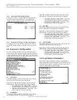
3.4 PUMP
CONFIGURATION
vFlow™ vs internal fl ow control pump can be controlled either
through temperature differential (Delta T) or can be set to
specifi c speed (fi xed; % of full speed for each heat and cool
stage).
Can be confi gured for either single pumping or parallel
pumping.
Confi gure temperature differentials at the thermostat for
vFlow™ units with an internal fl ow control pump.
Adjust the Pump Confi guration settings using the up/down
arrow buttons. Press the center button to select each item.
• Heating Delta T (default stored in control) –
valid range: 4 to 12ºF (in 1ºF increments)
• Cooling Delta T (default stored in control) –
valid range: 9 to 20ºF (in 1ºF increments)
Maximum Heat LWT (valid range based on specifi c model;
refer to model IOM). Minimum Cool LWT (valid range based
on specifi c model; refer to model IOM).
NOTE:
Refer to section 3.6.3 for multi-unit confi guration
instructions.
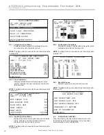
VARIABLE SPD INTERNAL
PUMP CONFIGURATION
LOOP OPTION PARALLEL
PUMP CONTROL DELTA T
HEATING DELTA T 7 F
COOLING DELTA T 10 F
MAXIMUM HEAT LWT 80 F
MINIMUM COOL LWT 40 F
PREVIOUS SELECT
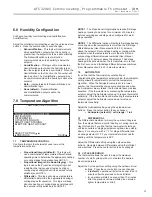
To control vs pump by fi xed speed, select ‘Pump Control’,
press , use down arrow to select ‘Fixed’, and press to
save.
Default stored in control. Valid range: 15% - 90% (in 1%
increments)
Heating Stage 1
Cooling Stage 1
Heating Stage 2
Cooling Stage 2
If Loop Option is set to ‘PARALLEL’, valid range changes to
50-90% (in 1% increments).
Содержание iGate ATC32U03
Страница 2: ...This page was intentionally left blank...


