


13
AT C 3 2 U 0 3 C o m m u n i c a t i n g , P ro g r a m m a b l e T h e r m o s t a t - I O M
R e v. : N o v e m b e r 3 , 2 0 1 7
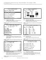
CONTROL DIAGNOSTICS - 2
HP SWITCH CL
LOC SWITCH CL
Y1 PHYSICAL INPUT ON
Y2 PHYSICAL INPUT OFF
W PHYSICAL INPUT OFF
O PHYSICAL INPUT ON
G PHYSICAL INPUT ON
H PHYSICAL INPUT OFF
EMERG SHUTDOWN OFF
NIGHT SETBACK OFF
OVR INPUT OFF
CONTROL VOLTAGE 26.4
PREVIOUS
CONTROL DIAGNOSTICS - 1
LT1 TEMP 38.1
LT2 TEMP 79.9
COMP DISCHARGE 157.7
ENTERING WATER 78.5
LEAVING WATER 73.3
HOT WATER EWT 121.5
LEAVING AIR 75.1
LOOP PUMP SPD 60%
LOOP PUMP WATTS 140
LOOP FLOW GPM 7.4
ECM BLOWER RPM 550
ECM TARGET CFM 800
ECM BLOWER STATIC 0.5
PREVIOUS NEXT
CONTROL CONFIGURATION
DIPSWITCH S1
1 ON UPS ENABLED
2 ON DUAL COMP STG 1
3 ON HEAT PUMP TSTAT
4 ON RV O THERMOSTAT
5 ON DEHUMID OFF
6 ON EH2 AUX HEAT
7 ON BOILERLESS
8 ON SEE DXM2 AOM
PREVIOUS NEXT
CONTROL CONFIGURATION
DIPSWITCH S2
1 ON \ ACCESSORY 1
2 ON ACCESSORY 2
3 ON/
4 ON \ ACCESSORY 2
5 ON ACTIVE W/ COMP
6 ON /
7 ON H DEHUM INPUT
8 ON FACTORY SETTING
PREVIOUS NEXT
CONTROL CONFIGURATION
DIPSWITCH S3
1 ON FACTORY SETTING
2 OFF HWG TEST OFF
3 OFF HWG SP 125
4 OFF HWG DISABLED
JW3 LT1 SETTING WELL
PREVIOUS
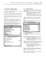
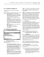
9.3 DIPSWITCH
CONFIGURATION
Dipswitch Confi guration mode allows the service personnel
to view the status of all dipswitch settings for the connected
communicating control (DXM2/AXM) at the thermostat.
Navigate between confi guration screens using the left/right
arrow buttons.
NOTE 1
: The unit control dipswitch settings cannot be
changed from the thermostat.
NOTE 2
: If multiple units are connected to one thermostat,
refer to section 9.6.
TT038 SN - - - - - 0 1 2 3
LAST 5 FAULTS
LT1 LOW WATER TEMP
NO FAULT
NO FAULT
NO FAULT
NO FAULT
NEXT
PREVIOUS SELECT
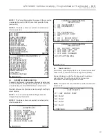
9.4 FAULT
HISTORY
Fault History mode displays the fi ve most recent stored fault
codes for the connected communicating control (DXM2).
Navigate between control fault codes using the up/down
arrow buttons. Press the center button to view more
information about the highlighted fault code.
NOTE
: If multiple units are connected to one thermostat, refer
to section 9.7.
NOTE 1
: The Pump Status will not be present if the connected
communicating control (DXM2) is not confi gured for Pump
(section 3.3).
NOTE 2
: If multiple units are connected to one thermostat,
refer to section 9.6.
Содержание iGate ATC32U03
Страница 2: ...This page was intentionally left blank...


