


7
AT C 3 2 U 0 3 C o m m u n i c a t i n g , P ro g r a m m a b l e T h e r m o s t a t - I O M
R e v. : N o v e m b e r 3 , 2 0 1 7
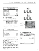
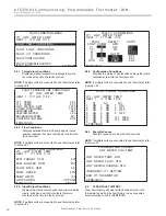
AIRFLOW SELECTION
CFM
HEAT STAGE 1 600
HEAT STAGE 2 750
AUXILIARY HEAT 850
EMERGENCY HEAT 850
COOL STAGE 1 525
COOL STAGE 2 700
COOL DEHUMID 1 425
COOL DEHUMID 2 550
CONTINUOUS FAN 350
HEAT OFF DELAY 60
COOL OFF DELAY 30
PREVIOUS NEXT
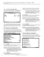
NOTE:
“Motorized Valve” used here refers to a two-position
motorized water valve, not to be confused with the modulating
motorized water valve found in the LOOP CONFIG.
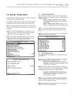
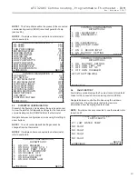
3.0 System Confi guration
Use the System Confi guration option on the start-up screen
to adjust critical equipment settings.
The System Confi guration information will be automatically
obtained from each communicating control in the system.
Note 1:
The Airfl ow Selection menu (section 3.1) will not be
present if the connected communicating control system has
no blower.
Note 2:
The Pump Confi guration menu (section 3.4) will
not be present if the connected communicating control is
confi gured for No Loop Confi guration (OTHER).
Note 3:
The Valve Confi guration menu (section 3.5) will
not be present if the connected communicating control is
confi gured for No Loop Confi guration (OTHER).
3.1 AIRFLOW
SELECTION
Adjust the airfl ow settings for each system operating mode
using the up/down arrow buttons. Press the center button to
select each item.
• Airfl ow Settings (defaults stored in control)
-
valid range: obtained from control (in 25 CFM
increments)
• Blower Off Delay (default 60 seconds) –
valid
range: 0 to 255 seconds (in 5 second increments)
NOTE 1:
The Airfl ow Settings will only be present if the
connected communicating control is confi gured for ECM
blower.
NOTE 2:
If multiple units are connected to one thermostat,
refer to section 3.6 for unit selection.
3.2 OPTION
SELECTION
This option allows the confi guration of heat pump options to
be modifi ed.
Adjust the Option settings using the up/down arrow buttons.
Press the center button to select each item.
• Motorized Valve (defaults stored in control) –
valid range: Off, On “On” delays compressor start
until the valve is fully open.
• Compressor ASCD (Anti-Short Cycle Delay
(default stored in control) –
valid range: 5 to 8
(in 1 minute increments)
NOTE 1:
The Compressor Anti-Short Cycle Delay setting
provides equipment protection by forcing the compressor to
wait a few minutes before restarting.
NOTE 2:
If multiple units are connected to one thermostat,
refer to section 3.6 for unit selection.
SYSTEM CONFIGURATION
AIRFLOW SELECTION
OPTION SELECTION
UNIT CONFIG TE026
PUMP CONFIGURATION
SELECT OPTION
PREVIOUS SAVE
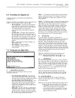
INSTALLER SETTINGS
THERMOSTAT CONFIG
SYSTEM CONFIG
ACCESSORY CONFIG
INPUT DEALER INFO
HUMIDITY CONFIG
TEMPERATURE CONTROL
DEMAND REDUCTION CNFG
SERVICE MODE
SETPOINT LIMITS
RESTORE DEFAULTS
DXM2 3.3
ATC32U02 C 1.0
SELECT OPTION
PREVIOUS
Содержание iGate ATC32U03
Страница 2: ...This page was intentionally left blank...


