


21
Flow Controller 3
R e v. : F e b u r a r y 9 , 2 0 1 6
Geothermal Closed Loop Design
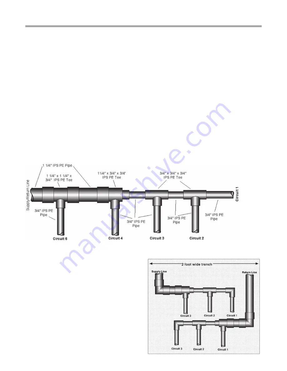
Figure 14: Typical “Laydown” Header
Figure 13b: Typical Header Through 5 Tons
gpm [36 l/m] to attain 2 fps [0.6 m/s] and since increasing
the flow through the last circuit would also require increasing
the flow through the other circuits at an equal rate as well,
we can estimate the flush flow requirements by multiplying
the number of circuits by 9.5 gpm [36 l/m] for 1-1/4” IPS. For
instance, a 5 circuit loop would require 5 circuits x 9.5 gpm/
circuit = 47.5 gpm [5 circuits x 36 l/m per circuit = 180 l/m
or 3.0 l/s] to attain flush flow rate. This is clearly is a difficult
flow to achieve with a pump of any size.
Header Layout - Generally header layouts are more cost
effective with short headers. This requires centrally locating
the header to all circuits and then bringing the circuits to the
header. One of the easiest implementations is to angle all
trenches into a common pit similar to a starburst. This layout
can utilize the laydown or ‘L’ header and achieves reverse
return flow by simply laying the headers down in a mirror
image and thus no extra piping or labor. Figure 14 details a
“laydown” header.
Inside Piping - Polyethylene pipe provides an excellent no
leak piping material inside the building. Inside piping fittings
and elbows should be limited to prevent excessive pressure
drop. Hose kits employing 1” rubber hose should be limited
in length to 10-15 feet [3 to 4.5 meters] per run to reduce
pressure drop problems. In general 2 feet of head [6 kPa]
pressure drop is allowed for all earth loop fittings which
would include 10-12 elbows for inside piping to the Flow
Controller. This allows a generous amount of maneuvering
to the Flow Controller with the inside piping. Closed cell
insulation (3/8” to 1/2” [9.5 to 12.7 mm] wall thickness)
should be used on all inside piping where loop temperatures
below 50°F [10°C] are anticipated. All barbed connections
should be double clamped.
Flow Controller Selection - The pressure drop of the
entire ground loop should be calculated for the selection
of the Flow Controller (a pressure drop spreadsheet is
downloadable from the web site). In general, if basic loop
design rules are followed, units of 3 tons [10.6 kW] or less
will require only 1 circulating pump (UP26-99). Units from
3.5 to 6 tons [12.3 to 21.1 kW] will require a two pump
system (2 - UP26-99). Larger capacity units with propylene
glycol as antifreeze may require 2 - UP26-116 pumps.
However, the UP26-116 should be avoided where possible,
as power consumption of the 26-116 is significantly higher
than the 26-99, which will affect heating and cooling
operating costs. In many cases, where pressure drop
calcuations may call for 3 - UP26-99 pumps, try substituting
2 - UP26-116 pumps. This makes the installation much
easier and reduces cost. Chart 2 shows the various pump
combinations.
Loop pressure drop calculation should be performed for
accurate flow estimation in any system including unit, hose
kit, inside piping, supply/return headers, circuit piping,
and fittings. Use Tables 6A through 6F for pressure drop
calculations using antifreeze and PE/rubber hose piping
materials.


