background image

15

844774

202154

832125

Part No.     Model
203104        -2
203105        -3
203104        -4
203105        -6

Part No.     Model
203106        -2
203107        -3
203106        -4
203107        -6

204809

Part No.     Model
861525        -2
861485        -3
861484        -4
861486        -6

Part No.     Model
867526        -2
867526        -3
867523        -4
867523        -6

Part No.     Model
NONE          -2
NONE          -3
867524        -4
867524        -6

867505

867535

867527

-2, -3, -4, & -6 Gear Trains

-7 Gear Train

861487

844774

832125

867526

-10 Gear Train

869629

847566

869634

202605

812164

202156

847566

869634

202605

812164

202158

847566

869634

202605

812164

202155

202157

Part No.     Model
844774        -2
844774        -3
844774        -4
844774        -6

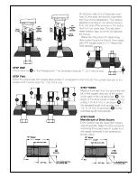
45 & 55

RIGHT ANGLE HEAD

TRANSDUCERIZED

GEAR TRAINS

PART NO.

202154
202155
202156
202157
202158
202605
203104
203105
203106
203107
204809
812164
832125
844774
847566
861484
861485
861486
861487
861525
867505
867523
867524
867526
867527
867535
869629
869634

Model

2
3
4
6

Model

7

10

QUANTITY

MODELS

-3

1

-
-
-
-

1

-

1

-

3
3
1
3
9
1

-

1

-
-
-
-
-
-

3

-
-

1
1

-4

1

-
-
-
-

1
1

-

3

-

3
1
3
9
1
1

-
-
-
-
-

3
1

-
-
-

1
1

-6

1

-
-
-
-

1

-

1

-

3
3
1
3
9
1

-
-

1

-
-
-

3
1

-
-
-

1
1

-2

1

-
-
-
-

1
1

-

3

-

3
1
3
9
1

-
-
-
-

1

-
-
-

3

-
-

1
1

-10

-
-
-

1
1
1

-
-
-
-
-

1
3
3
1

-
-
-

1

-
-
-
-

3

-
-
-

1

-7

-

1
1

-
-

1

-
-
-
-
-

1

-
-

1

-
-
-
-
-

3

-
-
-

3
1

-

1

NAME OF PART

Transducer Housing
Transducer Housing
Ring Gear 38T
Transducer Housing
Ring Gear 50T
Transducer
2nd Red. Spider
2nd Red. Spider
2nd Red. Gear 18T (incl. 844774)
2nd Red. Gear 15T (incl. 844774)
2nd Gear Pin
Ring Gear Pin
Gear Pin
2nd Red. Gear Bearing
Transducer Bearing
Spider 13T (incl. Pin)
Spider 19T (incl. Pin)
Spider -(incl. 832125)
Spider 13T (incl. Pin)
Idler Gear Pin
1st Red. Gear 17T (incl. 844774)
Rotor Pinion 16T
Idler Gear 21T (incl. 844774)
Idler Gear 11T & 22T
Spider
Ring Gear 50T
Retainer Ring

2nd Red. Spider (Incl. Spider, Gears and Pins)

201307
201308
201309
201308

1st Red. Spider (Incl. Spider, Gears and Pins)

861488

------------

Gear Train (Incl. 1st & 2nd Red. Spider, Gears and Pins)

201350
201351
201352
201353

Gear Train (Incl. 1st & 2nd Red. Spider, Gears and Pins)

------------
------------

Содержание 55NLTVC Series

Страница 1: ...er L Options Handle Transducer 55 Nutrunner 55 Series N T XX C L X Built in Socket S Gear Train Designation Specify Size Threaded Spindle T Output Drive Angle Terminations 2 3 4 6 7 10 X X X 3 8 1 2 4...

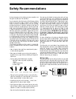
Страница 2: ...ing sockets make sure the air line is shut off and drained of air This will Safety Recommendations prevent the tool from operating if the throttle is accidently engaged When using right angle nutrunne...

Страница 3: ...d wrist supports are designed to reduce and moderate the effects of extended vibration exposure and repetitive wrist trauma Since they vary widely in design material thickness vibration reduction and...

Страница 4: ...RECOMMENDATIONS ON PAGES 2 3 BEFORE OPERATING A NUTRUNNER TORQUE ADJUSTMENT The 55NLTVC nutrunner is designed to develop maximum rated torque at 90 psig The torque setting is achieved by entering a nu...

Страница 5: ...867510 ballbearing No 867547 and driven gear by clamping the square drive in the vise Drive the right angle housing away from the square drive using a soft mallet Press the square drive end of the spi...

Страница 6: ...th the pockets machined in the ring gear Line up the hole in the ring gear with the hole in the transducer and install the pin No 812164 Transducer Wiring Connection NOTE Do not bend strike push or pu...

Страница 7: ...l Calibration Resistor Value in ohms of the torque monitor used The following is an example of a 55 series right angle tool a P head and a torque monitor with a 110 000 ohm calibration resistor The va...

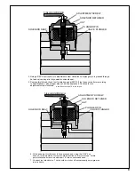
Страница 8: ...015 020 as shown A new plunger pin should be spaced as shown however a previously used plunger pin must be pressed to this dimension 2 Assemble the solenoid components as shown Solenoid retainer must...

Страница 9: ...JUSTMENT SCREW 5 64 HEX WRENCH SOLENOID SEAT VALVE PLUNGER SOLENOID RETAINER PLUNGER PIN HAT 4 Using a 5 64 hex wrench turn adjustment screw clockwise until plunger pin is pressed through hat and valv...

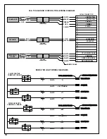
Страница 10: ...D SIGNAL V RED LED SIGNAL RED RED SOLENOID CAMBION CONNECTORS BLACK BLACK ARMOR CABLE 55 75 SOLENOID CONTROL TOOL WIRING DIAGRAM S S T T U U V V WHITE WHITE WHITE WHITE YELLOW LED COMMON GREEN LED RED...

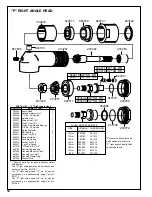
Страница 11: ...ng 1 2 x 5 8 Pinion Bearing upper Driven Gear Bearing Cap Housing incl 843589 Pinion Gear Housing Make Up Plate Housing Lock Nut Housing Clamp Ring Lock Pin Spring Cap Socket Lock Pin 3 8 Sq Dr Spindl...

Страница 12: ...844014 844016 844017 847272 864105 867520 867521 867522 867546 Angle Head Spindle Retainer Nut 1 2 Sq Dr Spindle Spindle Cap Driven Gear 14T Pinion Gear 9T Pinion Gear Needle Bearing 3 8 Sq Dr Spindl...

Страница 13: ...ke Up Plate Housing Lock Nut Housing Clamp Ring Grease Plug Spindle Ball Bearing Pinion Needle Bearing Bearing Cap Set Screw Spindle Needle Bearing T RIGHT ANGLE HEAD Denotes parts not included in sub...

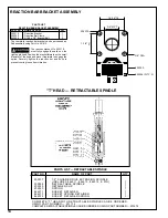
Страница 14: ...of the head and move it rearward to engage the spline Securely tighten the reaction bar and bolts to prevent coming loose from vibration CAUTION REACTION BAR BRACKET ASSEMBLY T HEAD RETRACTABLE SPINDL...

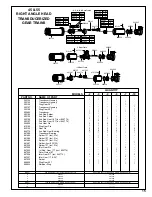
Страница 15: ...535 869629 869634 Model 2 3 4 6 Model 7 10 QUANTITY MODELS 3 1 1 1 3 3 1 3 9 1 1 3 1 1 4 1 1 1 3 3 1 3 9 1 1 3 1 1 1 6 1 1 1 3 3 1 3 9 1 1 3 1 1 1 2 1 1 1 3 3 1 3 9 1 1 3 1 1 10 1 1 1 1 3 3 1 1 3 1 7...

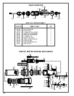
Страница 16: ...PLATE 1 203374 DRIVE SHAFT 1 203374 202396 619377 867536 203101 869572 843444 865352 203099 869569 863887 55NLTVC MOTOR HOUSING AND HANDLE 203259 Neg Common 203350 Pos Common 203450 863241 203369 203...

Страница 17: ...Seat Gasket Solenoid Seat Solenoid Retainer incl 863241 Air Inlet Valve Piston incl 866399 Shut off Valve incl 203379 Valve Seal Valve Cap incl 847710 Throttle Valve Spring Bushing Wire Bundle 19 pin...

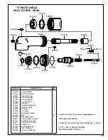
Страница 18: ...RING INTERNAL HEX SPINDLE DRIVE SPINDLE GEAR SPLINE PROTECTOR CLIP RETAINING RING SET SCREW DRIVE SPINDLE BALL BALL BEARING LOCK PIN SPRING HOUSING MAKE UP PLATE HOUSING LOCK NUT HOUSING CLAMP RING PI...

Страница 19: ...11 864712 204346 867997 204344 867924 204349 DESCRIPTION ANGLE HEAD DRIVE SPINDLE BEARING CAP HOLD SPINDLE CLAMP RING CLAMP NUT SPRING NEEDLE BEARING DRIVEN GEAR PINION O RING RETAINING RING BALL BALL...

Страница 20: ...4 867524 6 2 3 4 6 GEAR TRAINS 869629 TRANSDUCERIZED ONLY 847566 869634 202605 812164 Part No Model 844774 2 844774 3 844774 4 844774 6 QUANTITY MODELS 3 1 1 1 1 3 1 3 9 1 1 3 1 1 4 1 3 1 1 1 3 1 3 9...

Страница 21: ...21...

Страница 22: ...22 NOTES...

Страница 23: ...23 NOTES...

Страница 24: ...24 670 Industrial Drive Lexington SC 29072 Phone 803 359 1200 Fax 803 359 2013...

Отзывы: