


5
SERVICE INSTRUCTIONS
DISASSEMBLY — GENERAL
Disconnect tool from air supply. Clamp the right angle head
in a vise and loosen (left hand threads) the motor housing.
Hold the tool in a vertical position with the right angle head
up. Unscrew (left hand threads) and remove the head, and
transducer housing from the motor housing. Disconnect the
wire connector, No. 202183, at the transducer and remove
the transducer and gear train from the motor housing. Slip
the complete motor unit out the front of the housing.
Clamp the angle head in the vise and unscrew (left hand
threads) the right angle housing lock nut, No. 867521, to
remove the transducer housing.
"M" Right Angle Head
Using a suitable spanner wrench, unscrew (left hand threads)
the bearing cap, No. 864396. Remove the square drive
spindle, No. 867643, ball bearing, No. 842517, and driven
gear by clamping the square drive in the vise. Drive the right
angle housing, No. 867506, away from the square drive
using a soft-faced mallet. The ball bearing can now be
removed by pressing the square drive end of the spindle
through the bearing I.D. Press the smaller end of the spindle
through the gear to remove the driven gear. Screw a 1/40
NC bolt into the pinion gear. Clamp the head of the bolt in the
vise and use a soft-faced mallet to drive the housing off the
gear. If this method fails, it will be necessary to use a suitable
puller.
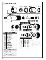
"P" Right Angle Head
Using a suitable wrench, unscrew (left hand threads) the
bearing cap, No. 203250. Remove the square drive spindle,
No. 203249, ball bearing, No. 842517 and driven gear, No.
203251, by clamping the square drive in the vise. Drive the
right angle housing, No. 203247, away from the square
drive using a soft-faced mallet. Remove the spindle retainer
nut, No. 203248, with a wrench. The ball bearing can now
be removed by pressing the square drive end of the spindle
through the gear to remove the driven gear. Screw a 1/40
NC bolt into the pinion gear. Clamp the head of the bolt in
the vise and use a soft-faced mallet to drive the housing off
the gear. If this method fails, it will be necessary to use a
suitable puller.
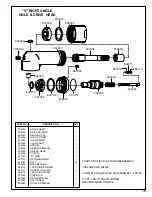
"T" Right Angle Head
Loosen the bearing cap lock screw, No. 867997, and
unscrew (left hand threads) the bearing cap, No. 867509.
Remove the square drive spindle, No. 867510, ball bearing,
No. 867547, and driven gear by clamping the square drive
in the vise. Drive the right angle housing away from the
square drive using a soft-mallet. Press the square drive end
of the spindle through the bearing I.D. to remove the ball
bearing. The driven gear may be removed by pressing the
smaller end of the spindle through the gear. Remove the
grease plug, No. 867546, and , using a suitable driver, drive
the pinion gear out of the right angle housing.
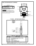
Gear Train 2, 3, 4, 6, & 10
Important: Do not bend, strike, push or pull in any way that
will cause strain in the plastic coated area of the transducer.
Remove the gear train from the front of the ring gear.
Remove the retainer ring and ball bearing. Drive roll pin, No.
812164, in far enough to clear the ring gear and slip the ring
gear off the transducer.
Gear Train
Important: Do not bend, strike, push or pull on the plastic
coated area of the transducer. Drive roll pin, No. 812164, in
far enough to clear the ring gear. Remove the ring gear and
align the idler gears with the pockets machined in the ring
gear. Slip the spider assembly out the rear of the ring gear.
Remove the retainer ring and ball bearing and drive the roll
pin into the bearing bore.
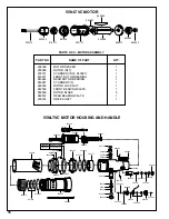
Motor Unit
Clamp the cylinder lightly in a vise with the gear end of the
rotor up. Note: Rotor pinion, No. 867524, used on the and
models should be removed at this time. Drive the rotor out
of the front rotor bearing, No. 619377. Be careful not to
damage the rotor. The front bearing plate, No. 867536,
cylinder, and rotor blades, No. 203219, can now be re-
moved from the rotor. Clamp the rotor in the vise with the
rear bearing plate up. After unscrewing the bearing lock nut,
No. 865352, the rotor can be driven out of the rear rotor
bearing.
Motor Housing
Clamp the flats of the motor housing in the vise and use a
strap wrench to unscrew the handle, No. 202182. Discon-
nect the wire bundle from the cable connector, No. 202183.
Remove solenoid retainer, No. 203369, with wrench and
remove solenoid, No. 203363. Remove retainer ring, No.
203053 and rear light ring, No. 203263. Unplug P.C. Board,
and remove from rear of tool. Remove set screw, No.
813315 and remove front light ring, No. 203262. Remove
exhaust deflector, No. 203261, exhaust screen, No. 202177,
and muffler, No. 202012, from the rear of the housing.
Remove throttle valve cap, No. 864531, valve cap, No.
203380 and shut-off valve cap, No. 203550 with screw-
driver to check seals and "O"-rings.
Содержание 55NLTVC Series
Страница 21: ...21...
Страница 22: ...22 NOTES...
Страница 23: ...23 NOTES...
Страница 24: ...24 670 Industrial Drive Lexington SC 29072 Phone 803 359 1200 Fax 803 359 2013...