6
MOTOR DISASSEMBLY
Use a soft-faced hammer to drive the rotor out of the front rotor
bearing, No. 203489. This will allow the cylinder and five (5)
rotor blades to be removed from the rotor. Set the rear bearing
plate on the vise jaws with the rotor facing down. Use a 7/32"
punch to drive the rotor out of the rear rotor bearing.
BACKHEAD DISASSEMBLY
Unscrew and remove the inlet bushing, No.203355, for inspec-
tion and cleaning of the air inlet screen, No.869171. Replace
the screen if clogged or torn.The throttle valve and related
components may be removed by unscrewing the valve caps, (2)
No. 203362 and No. 203360. To remove solenoid, unscrew
solenoid retainer No. 203369. Lift the solenoid seat from
backhead while holding solenoid wires to the side. The sole-
noid can then be removed while feeding wires through the
backhead.
REASSEMBLY—GENERAL
All parts except the electronics should be washed in a solvent
and inspected for damage or wear. Particular attention should
be given to all bearings, gears, gear pins, and rotor blades as
failure of these parts could cause damage to more expensive
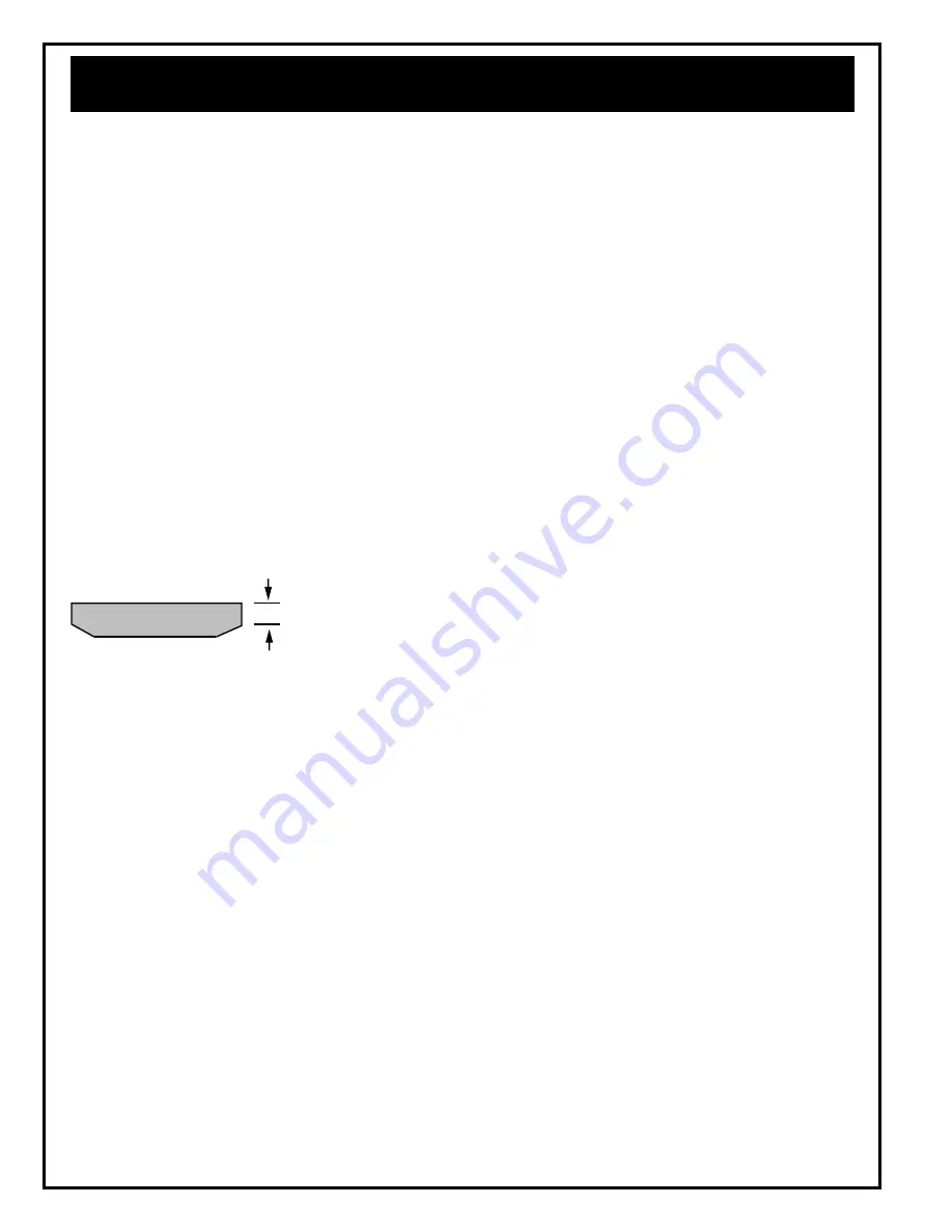
parts. Rotor blades should be replaced at every repair cycle or
if they measure less than 3/16" (4.75mm) on either end.
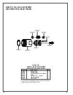
NOTE: The "K" and "M" angle heads, gear case and backhead
should be tightened to 40ft. lbs. (54Nm). The "P" angle head
has a lock ring that should be tightened to 20 ft. lbs. (27Nm).
Inspect and replace any "O" rings or seals that show signs of
wear or deterioration. During reassembly all parts should
receive a coating of NLGI 2-EP grease. Reassembly of all of the
various sub-assemblies is in the reverse order of disassem-
bly; however, the following paragraphs list some of the more
important reassembly procedures.
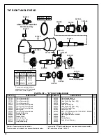
"K" RIGHT ANGLE HEAD REASSEMBLY
Slip pinion needle bearing, No. 869864, (unstamped end first)
on the pinion, No. 202200, and press (press on the bearing's
stamped end) the bearing to a depth of 7/8"(22mm) from the
face of the bearing bore. Install pinion ball bearing, No. 847846
and bearing retainer, No. 863564, in the head and tighten retainer
securely using the 5/8"(16mm) hex nut and 5/8"(16mm) deep
socket. Using a suitable driver through the hole in the top of the
head, drive the pinion back to make sure it is seated properly in the
head.
"M" RIGHT ANGLE HEAD REASSEMBLY
Assemble the spindle and related components in the head and
securely tighten (left hand threads) the bearing cap, No. 864396.
Assemble pinion needle bearing, No. 863360, to the pinion.
The stamped end of bearing faces towards hex end of pinion.
Use bearing spacer, No. 869050, to press the bearing into the
angle head to the correct depth. Install ball bearing, No.
847846, and bearing retainer, No. 863564, in the head and
tighten retainer securely using the 5/8"(16mm) hex nut and 5/
8"(16mm) deep socket.
"P" Right Angle Head
Assemble the spindle and related components in the head and
securely tighten (left hand threads) the bearing cap No. 203250.
Press the pinion needle bearing No. 203253, (press on the
bearing's stamped end) into the head along with pinion No.
203440, to a depth of 1.250" (31.75mm) from the shoulder of
the housing. Install ball bearing No. 202197. Retighten hous-
ing lock nut with proper wrench to 20 ft. lbs.
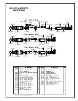
MOTOR REASSEMBLY
Assemble the rear rotor bearing and rear bearing plate (press
on the bearing's inner race) onto the rear rotor shaft until there
is approximately .0015" clearance between the plate and rotor.
Assemble the five (5) rotor blades, cylinder, front bearing plate,
and front rotor bearing (press on the bearing's inner race) to the
rotor assembly. After final assembly, the cylinder should be
held firmly, but not tightly between the two (2) bearing plates and
the rotor should turn freely and not rub either bearing plate.
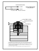
SOLENOID ADJUSTMENT
Refer to pages 7 and 8 for solenoid adjustment.
SAFETY CHECK
After repair or replacement of parts, tools equipped with an
automatic shut-off device should be tested to verify that the
device is functioning properly. The torque setting entered into
the torque control monitor must not exceed maximum torque
range of tool or the automatic shut-off device will not function
and the tool will operate as a stall tool. Operator should be
prepared to resist torque reaction until throttle is released.
SERVICE INSTRUCTIONS
Must be replaced if less than
3/16" (4.7mm) on either end.

