4
OPERATING INSTRUCTIONS
FOR YOUR SAFETY AND THE SAFETY OF OTHERS, READ AND UNDERSTAND THE
SAFETY RECOMMENDATIONS BEFORE OPERATING A NUTRUNNER.
TORQUE ADJUSTMENT
The 40NLTVC & 40RNLTVC nutrunners are designed to de-
velop maximum rated torque at 90 psig. The torque setting is
achieved by entering a number within the tool's torque range
into the torque control monitor. See catalog for torque range of
tool.The torque setting entered into the torque control monitor
must not exceed maximum torque range of tool or the automatic
shut-off device will not function and the tool will operate as a stall
tool. Operator should be prepared to resist torque reaction until
throttle is released.
THROTTLE POSITION
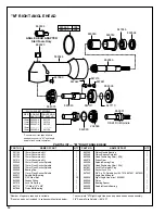
"K" & "M" Right Angle Head
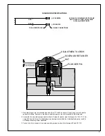
Both the "K" & "M" heads are threaded to the gear case. Throttle
positioning is accomplished by using shims between the head
and the gear case as required to properly position the throttle
lever with respect to the head to prevent hand entrapment. (See
Torque Reaction page2).
Retighten head with proper wrench to a torque higher than the
torque rating of the tool.
"P" Right Angle Head
The throttle lever may be repositioned to accomodate proper
location for task and to avoid hand entrapment. The "P" head
is splined to the gear case. Repositioning of the angle head is
done by loosening housing lock nut No. 203438 (left hand
threads), and lifting angle head enough to disengage the
spline and turning to position desired. Retighten housing lock
nut with proper wrench to 20 ft. lbs.
AIR SUPPLY
For maximum performance, use a 3/8" I.D. air hose no longer
than 8' in length. If additional length is required, a 1/2" or larger
hose should be connected to the 3/8" hose.
Being careful to avoid endangering adjacent personnel or
yourself, the air hose should be cleared of accumulated dirt and
moisture. Then one (1) teaspoonful of 10W machine oil should
be poured into the tool's air inlet before connecting the hose to
the tool.
LUBRICATION
An automatic in-line filter-lubricator is recommended as it
increases tool life and keeps the tool in sustained operation.
The in-line lubricator should be regularly checked and filled
with a good grade of 10W machine oil. Proper adjustment of the
in-line lubricator is performed by placing a sheet of paper next
to the exhaust ports and holding the throttle open approximately
30 seconds. The lubricator is properly set when a very light stain
of oil collects on the paper. Excessive amounts of oil should be
avoided.
Application of the tool should govern how frequently it is
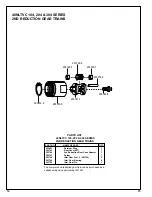
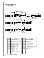
greased. It is recommended that the idler gears and angle
gears receive a generous amount of NLGI 2-EP grease after 40
hours of operation.
The angle head must be removed (left hand threads) from the
gear case and grease applied through the hex in the gear
spider to lubricate the idler gears. Grease is applied to the
angle gears through the grease fitting located in the angle head
housing. Use only a low pressure grease gun.
STORAGE
In the event that it becomes necessary to store the tool for an
extended period of time (overnight, weekend, etc.), it should
receive a generous amount of lubrication and run for a few
seconds until the oil is distributed throughout the tool. The tool
should be stored in a clean and dry environment.

