background image

2

Safety Recommendations

For your safety and the safety of others, read and understand the
safety recommendations and operating instructions before operat-
ing a nutrunner.

Always wear protective equipment:

For additional information on eye protection and face protection,
refer to Federal OSHA Regulations, 29 Code of Federal Regula-
tions, Section 1910.133., Eye and Face Protection, and American
National Standards Institute, ANSI Z87.1, Occupational and Edu-
cational Eye and Face Protection. Z87.1 is available from the
American National Standards Institute, Inc., 11 West 42nd Street,
New York, N.Y. 10036.

Hearing protection is recommended in high noise areas 85 dBA or
greater. The operation of other tools and equipment in the area,
reflective surfaces, process noises and resonant structures can
substantially contribute to, and increase the noise level in the area.
Excessive air pressure above 90 PSIG or worn motor components
can also increase sound level emitted by tool. Proper hearing
conservation measures, including annual audiograms and training
in the use and fit of hearing protection devices may be necessary.
For additional information on hearing protection, refer to Federal
Regulations, Section 1910.95, Occupational Noise Exposure, and
American National Standards Institute, ANSI S12.6, Hearing Pro-
tectors.

Cleco nutrunners are designed to operate on 90 psig (6.2 bar)
maximum air pressure. If the tool is properly sized and applied,
higher air pressure is unnecessary. Excessive air pressure in-
creases the loads and stresses on the tool parts, sockets, and
fasteners and may result in breakage. Installation of a filter-
regulator-lubricator in the air supply line ahead of the tool is
recommended.

Before the tool is connected to the air supply, check the throttle for
proper operation (i. e., throttle moves freely and returns to closed
position). Being careful not to endanger adjacent personnel, clear
the air hose of accumulated dust and moisture. Before connecting
a tool to the air hose, removing a tool from service or changing
sockets, make sure the air line is shut off and drained of air. This will
prevent the tool from operating if the throttle is accidently engaged.

CAUTION

!

Personal hearing protection is 
recommended when operating 
or working near this tool.

WARNING

!

Impact resistant eye protection 
must be worn while operating 
or working near this tool.

When using right angle nutrunners, be sure the throttle is posi-
tioned relative to the angle head so that the throttle will not become
wedged against an adjacent object in the "ON" position due to
torque reaction. The angle head may be repositioned with respect
to the lever to accommodate proper location for task. If tool is to be
reversed, locate throttle lever in a neutral position that will prevent
entrapment. Refer to operating instructions for additional informa-
tion.

It is essential for safe operation that any operator of a nutrunner use
good balance, sure footing, and proper posture in anticipation of a
torque reaction.

Tools with clutches can stall rather than shut-off if adjusted over
maximum power output of tool, or if there is a drop in air pressure.
Operator must then resist stall torque until throttle is released.

Tool balance arms are available to absorb the torque reaction of the
tool while balancing the weight of the tool for improved ergonomic
applications.

Some individuals may be susceptible to disorders of the hands and
arms when performing tasks consisting of highly repetitive motions
and/or exposure to extended vibration. Cumulative trauma disor-
ders such as carpal tunnel syndrome and tendonitis may be caused
or aggravated by repetitious, forceful exertions of the hands and
arms. Vibration may contribute to a condition called Raynaud's
Syndrome. These disorders develop gradually over periods of
weeks, months, and years. It is presently unknown to what extent
exposure to vibrations or repetitive motions may contribute to the
disorders. Hereditary factors, vasculatory or circulatory problems,
exposure to cold and dampness, diet, smoking and work practices
are thought to contribute to the conditions.

Any tool operator should be aware of the following warning signs
and symptoms so that a problem can be addressed before it
becomes a debilitating injury. Any user suffering prolonged symp-

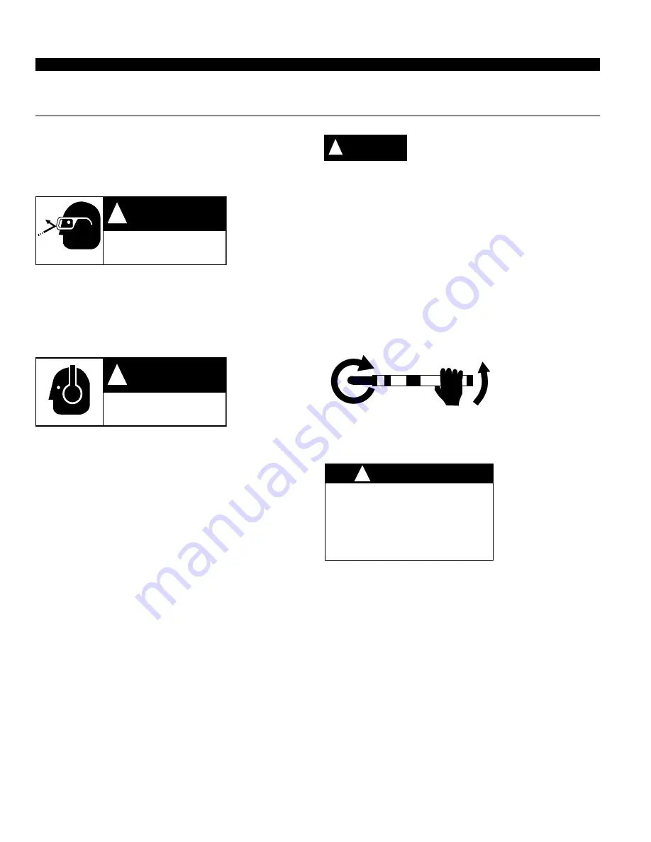
Spindle Rotation

Torque Reaction

Repetitive work motions and/or vibration
may cause injury to hands and arms.

Use minimum hand grip force consistent
with proper control and safe operation.
Keep body and hands warm and dry.
Avoid anything that inhibits blood circulation.
Avoid continuous vibration exposure.
Keep wrists straight.

WARNING

!

Avoid repeated bending of wrists and hands.

CAUTION

!

Содержание 35 Series

Страница 1: ...sion Lights Positive VP Options Handle 35 Nutrunner 35 Series N C T XX L 20 Built in Socket S Ext Housing E Gear Train Designation 15D 30D 15 30 Specify Size Threaded Spindle T Output Drive Angle Terminations M K 5 7 10 20 E XX 4 25 Magnetic M 1 4 3 8 2 3 NORTH AMERICA EUROPE P O Box 1410 Lexington SC 29071 Postfach 30 D 73461 Westhausen ...

Страница 2: ...ing or working near this tool WARNING Impact resistant eye protection must be worn while operating or working near this tool When using right angle nutrunners be sure the throttle is posi tioned relative to the angle head so that the throttle will not become wedged against an adjacent object in the ON position due to torque reaction The angle head may be repositioned with respect to the lever to a...

Страница 3: ...er each period of operation exercise to increase blood circu lation Keep tool well maintained and replace worn parts Work gloves with vibration reducing liners and wrist supports are available from some manufacturers of industrial work gloves Tool wraps and grips are also available from a number of different manufacturers These gloves wraps and wrist supports are de signed to reduce and moderate t...

Страница 4: ...t every acceptable safety practice is offered herein or that abnormal or unusual circumstances may not warrant or require additional procedures Your work may require additional specific safety procedures Follow these procedures as required by your company Warning Labels The warning labels found on these tools are an essential part of this product Labels should not be removed Labels should be check...

Страница 5: ...teaspoonful of 10W ma chine oil should be poured into the tool s air inlet before connecting the hose to the tool LUBRICATION An automatic in line filter lubricator is recommended as it increases tool life and keeps the tool in sustained opera tion Thein linelubricatorshouldberegularlycheckedand filled with a good grade of 10W machine oil Proper adjustment of the in line lubricator is performed by...

Страница 6: ...3353 very carefully to prevent damaging the wiring Unscrew left hand threads transducer housing and lift carefully feeding the wiring through the hole in the backhead To remove motor assembly tap backhead lightly on a soft surface K RIGHT ANGLE HEAD DISASSEMBLY To disassemble the right angle head unscrew the spindle bearing cap This will permit the removal of the spindle assem bly The pinion beari...

Страница 7: ...nd threads the bearing cap No 864396 Use bearing spacer No 869050 to press the pinion needle bearing No 863360 press on the bearing s stamped end in the head Install ball bearing No 847846 and bearing retainer No 863564 in the head and tighten retainer securely using the 5 8 hex nut and 5 8 deep socket 15 30 ANGLE HEAD REASSEMBLY Install a pinion needle bearing No 847746 on the pinion and press pr...

Страница 8: ... 015 020 as shown A new plunger pin should be spaced as shown however a previously used plunger pin must be pressed to this dimension 2 Assemble the solenoid components as shown Solenoid retainer must be torqued to 10 to 12 ft lbs using 242 Loctite Note Overtightening may damage solenoid body Undertightening may result in air leakage that may affect operation 3 Connect tool to air supply Air suppl...

Страница 9: ...sed Continue to turn adjustment screw clockwise Note Do not exceed 76 in lbs torque ADJUSTMENT SCREW 5 64 HEX WRENCH SOLENOID SEAT VALVE PLUNGER 6 While keeping throttle lever fully depressed and using the 5 64 hex wrench turn adjustment screw counterclockwise until motor stops At this point rotate the screw an additional 1 2 turn counterclockwise 7 Connect tool electronics Tool should now shut of...

Страница 10: ...he torque monitor used The following is an example of a 35 series right angle tool and a torque monitor with a 110 000ohm calibration resistor The values are FS 37 7 ft lbs Rbr 700ohm Vo 002 Rcal 110 000ohm 700ohm 1 1 FS X X 79 3 2 110 000ohm 700ohm 002 2 Calibration Value 37 7 793 29 9 ft lbs Calculated calibration value should be doubled if a torque monitor designed for use with a 350ohm bridge ...

Страница 11: ...MON U GREEN LED SIGNAL V RED LED SIGNAL RED RED SOLENOID CAMBION CONNECTORS BLACK BLACK ARMOR CABLE 35 40 SOLENOID CONTROL TOOL WIRING DIAGRAM S S T T U U V V WHITE WHITE WHITE WHITE YELLOW LED COMMON GREEN LED RED LED TOOL RECEPTACLE CABLE CONNECTORS 24V COMMON R R R 203349 POSITIVE COMMON PC BOARD INDICATOR LIGHT WIRING DIAGRAMS S S T T U U V V WHITE WHITE WHITE WHITE YELLOW LED COMMON GREEN LED...

Страница 12: ...ndle incl 844013 844016 844014 1 4 Sq Dr Spindle incl 202987 847853 202986 10mm Flush Socket Spindle 13mm Flush Socket Spindle 15mm Flush Socket Spindle 1 2 Flush Socket Spindle 9 16 Flush Socket Spindle PART NO PART NO NAME OF PART NAME OF PART QTY QTY 201004 201005 201006 201007 201008 202195 202196 202197 202198 202199 202200 202201 202266 202267 202268 202298 202299 202300 202301 202302 1 1 1 ...

Страница 13: ...all Grease Fitting Lock Pin Spring O Ring 1 2 x 5 8 Pinion Ball Bearing Pinion Needle Bearing Pinion Bearing Retainer Head Positioning Shim 008 Driven Gear Spindle Bearing Cap Head Positioning Shim 004 Lock Pin Retainer Plug Socket Lock Pin 3 8 Sq Dr Spindle incl 847219 867641 867642 Angle Head Adapter Right Angle Head incl 843589 Pinion Bearing Spacer 3 8 24 Threaded Spindle Spindle Needle Bearin...

Страница 14: ...1 847746 Pinion Needle Bearing 2 847747 Gear Spacer 005 PART NO NAME OF PART QTY PARTS LIST 15 ANGLE HEAD Number of spacers required is variable The complete D model angle head can be purchased as a subassembly specify socket gear size when ordering using the following part number 15 201000 15 ANGLE HEAD 864751 847747 847095 812164 864201 864202 864264 L 842980 SOCKET GEAR Hex Size Part No 5 16 20...

Страница 15: ...w 1 847746 Pinion Needle Bearing 2 847747 Gear Spacer 005 PART NO NAME OF PART QTY PARTS LIST 30 ANGLE HEAD Number of spacers required is variable The complete D model angle head can be purchased as a subassembly specify socket gear size when ordering using the following part number 30 201001 30 ANGLE HEAD 864751 847747 847095 812164 864202 864264 L 842980 SOCKET GEAR Hex Size Part No 5 16 202129 ...

Страница 16: ... 1st Red Gear 15T incl 867925 10 2nd Red Gear 15T 10 1st Red Spider incl 884125 10 2nd Red Spider incl 832128 5 7 20 1st Red Gear Bearing 5 7 20 1st Red Gear Pin 10 1st Red Gear Bushing 5 1st Red Gear 19T incl 867921 5 1st Red Spider incl 867922 7 1st Red Gear 17T incl 867921 10 Pinion Spacer 7 1st Red Spider incl 867922 10 1st Red Gear Pin 1 1 1 1 1 1 1 3 3 1 1 3 3 1 1 1 3 1 1 3 3 1 1 3 3 3 3 1 3...

Страница 17: ...R 847609 869788 812165 619377 202719 203124 203131 202718 203116 5 10 20 6T 203117 7 9T Name of Part Front Bearing Plate Rear Bearing Plate Drive Shaft 5 7 20 6T Drive Shaft 7 9T Cylinder Rotor Front Ball Bearing Cylinder Pin Rear Ball Bearing Rotor Blades Qty 1 1 1 1 1 1 1 1 1 5 PARTS LIST 35 SOLENOID NUTRUNNER MOTOR ASSEMBLIES ...

Страница 18: ... Parts included in light kit 201409 203353 844306 203036 864665 864665 843518 843518 847282 203055 Neg Com 203349 Pos Com 203057 203056 203357 863241 203369 203363 203365 203368 203367 844265 203366 202410 867877 203358 847426 203418 844306 203362 844060 844307 832207 203361 844307 203359 203360 203354 869171 203355 203356 844111 203450 202885 847445 202701 202720 812165 847426 864271 203366 20336...

Страница 19: ...19 NOTES ...

Страница 20: ...20 670 Industrial Drive Lexington SC 29072 Phone 803 359 1200 Fax 803 359 2013 ...

Отзывы: