


COLLABORATE Versa Lite CT
8
QSG-0091-001 v1.0 June 2020
Quick-Start Guide
Under-the-Table Mount
1. Select your hardware based on your specific installation needs.
2. Determine location for the mount.
3. Using expander as a guide (and level if needed), mark four mounting hole
locations with a pencil.
4. Determine proper depth and diameter, and drill four pilot holes for the #6 or
M3.5 screws.
5. Align mounting holes on expander mounting ears with pilot holes.
6. Insert four #6 or M3.5 screws and tighten
7. Align mounting holes on expander mounting ears with pilot holes.
8. Insert four #6 or M3.5 screws and tighten.
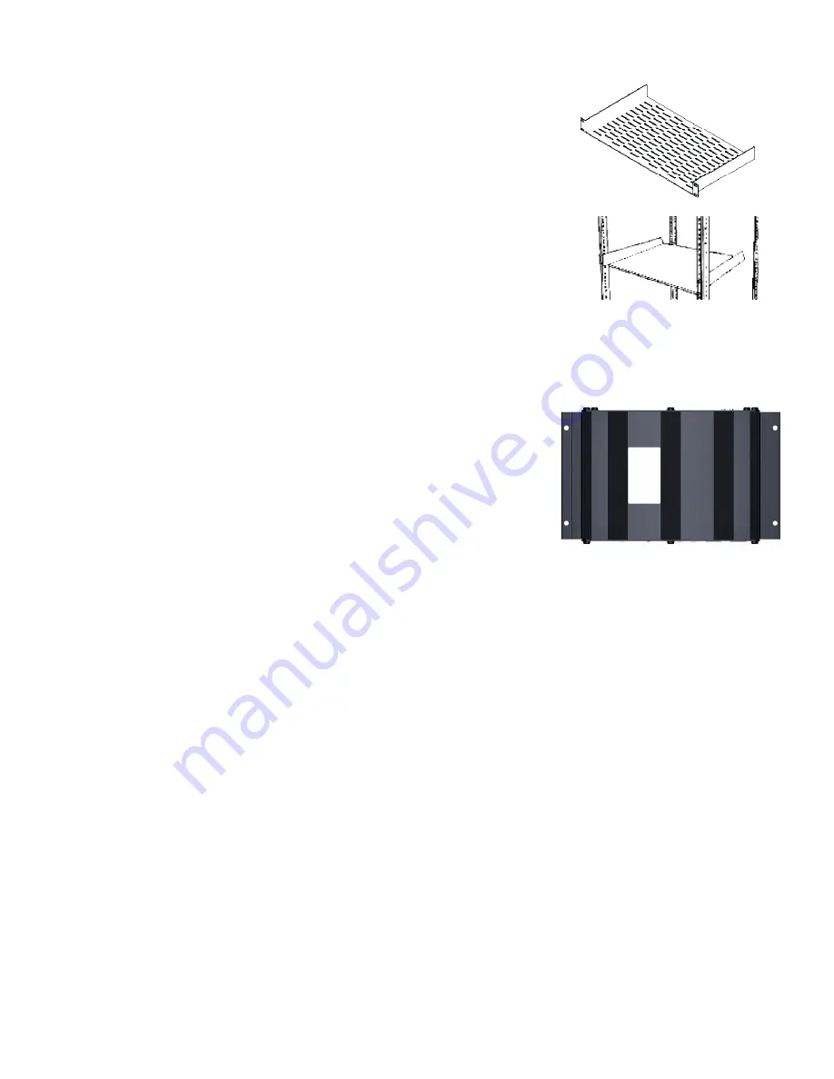
Rack Shelf Mount
ClearOne offers a standard 1U rack shelf with 20lb (9kg) weight capacity.
1. Determine location for rack shelf.
2. Align mounting holes on rack shelf mounting ears with holes on the rack (at
determined location).
3. Insert the four #10-32 screws included with the ClearOne 1U rack shelf (or
proper screws for your third-party mount) and tighten.
Note:
Remove pre-installed mounting ears on expander to fit up to 3 expander
units side-by-side on a single ClearOne 1U rack shelf.
4. Torx drive screws secure the pre-installed mounting ears to the main body of
the expander unit. Remove them with a Torx T15 screwdriver. (optional)
5. Secure expander unit(s) to the rack shelf. You must supply your own hardware
(four #6 or M3.5 screws) for securing the expander(s).
Wall Mount
Mounting hardware is not provided. Select your own hardware based on your specific installation needs.
1. Determine location for the mount.
2. Using expander as a guide (and level if needed), mark four mounting hole locations with a pencil.
3. Drill four pilot holes for fasteners/anchors using proper size drill bits.
4. Install fasteners/anchors.
5. Align mounting holes on expander mounting ears with pilot holes.
6. Insert four #6 or M3.5 screws and tighten.
Note:
Anchors and screws to mount the expander are not provided. The installer must select them for the wall mate-
rial that supports the expander. Exercise care when you drill and install anchors so wall material does not tear out and
weaken the attachment.
Above The Ceiling
Select hardware based on your specific installation needs.
Note:
It is the installer’s responsibility to ensure that the installation and cable routing complies with local safety codes.
1. Determine location for the mount, and where to route cables.
Mark location where you want to route cables through with a
pencil (on finished side of ceiling tile) if you need to cut a hole.
2. Remove affected ceiling tile and adjacent tiles required for access.
3. Install fasteners/anchors.
4. Install expander unit at determined location.
5. Use drywall saw to cut hole into finished side of ceiling tile at marked location.
Front Panel
Back Panel


