


COLLABORATE Versa Lite CT
10
QSG-0091-001 v1.0 June 2020
Quick-Start Guide
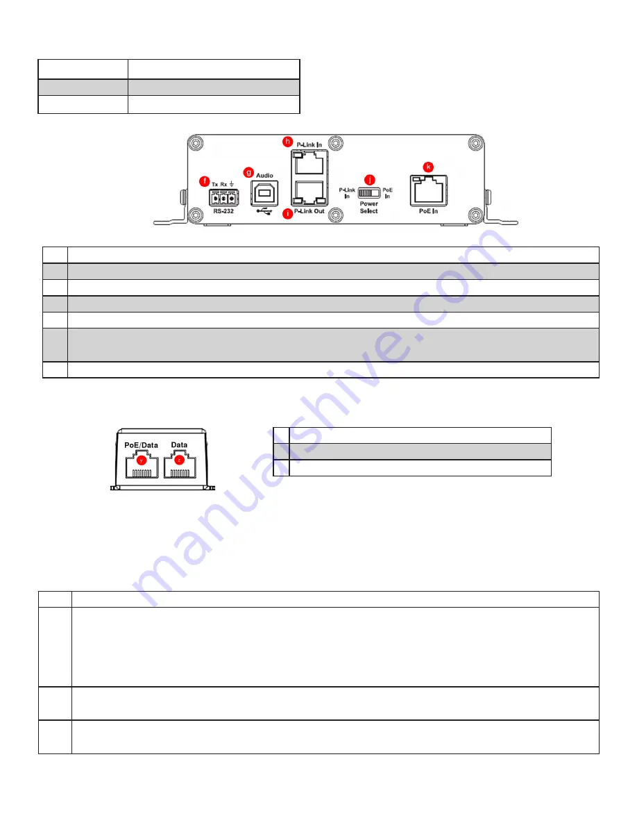
Figure 3. COLLABORATE Versa USB Back Panel
Description
f
RS-232.
Not used with Versa Lite CT.
g
USB Type B connector.
Connects to Versa USB.
h
P-Link In. RJ45 connector.
Not used with Versa Lite.
i
P-Link Out. RJ45 connector.
Connects to BMA CTH.
j
Power Select sliding switch.
Position determines power source – left for P-Link In or right for PoE in.
With a Versa Lite CT, this switch is set for PoE In.
k
PoE In. RJ45 connector.
Connects to the PoE Injector.
Power Indicator
LED Color
Meaning
Not lighted
Off - not powered
Solid Blue
Powered
PoE Injector
Description
y RJ45 connector. Used to provide power to Versa USB
z RJ45 connector. Not used.
Figure 4. PoE Injector Connectors
b. Steps to Connect
Step Actions
1.
Complete this step NOW if you did not when you installed the BMA CTH.
On the BMA CTH back plane:
•
With speaker wire (not included),connect the loudspeakers to the Phoenix Euroblock connectors (a)
• Move the Power Select sliding switch (c) to the right, towards the P-Link In connector (d)
2.
On the Versa USB back panel
Set the Power select switch (j) towards PoE In.
3.
With a 50’ CAT6 cable (provided)
Connect the BMA CTH P-Link In connector (d) to the Versa USB P-Link Out connector (i).
In the following instructions, the letter references such as “(a)” refer to points on figures 1, 3, and 4.
Before you connect the devices, download CONSOLE AI Lite software from www.clearone.com/console-ai-lite-
documents.


