12
WOBBLE
:
•
Ceiling fans are designed to move during operation because they are not generally rigidly mounted
•
Movement of a couple of centimetres is acceptable for safe operation.
•
Balancing kits included should be used to adjust the balancing when first installed.
NORMAL WEAR AND TEAR
:
Threaded components working slighting loose or blade carriers even slightly bent due to
vigorous cleaning or bumping can cause extra wobble and noise.
THIS IS NOT COVERED UNDER
WARRANTY
, however, a little care and maintenance can reduce or prevent this problem.
REMOTE CONTROL SETTINGS AND OPERATION FOR DC FANS:
The Hand-Held Remote-Control System is equipped with a learning frequency function which has code
combinations to prevent potential interference from other remote units. The frequency on your Receiver
and Transmitter units have been pre-set at the factory. If the remotes need programming, please follow
the below instructions.
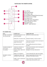
PAIRING THE REMOTE:
1.
Using the wall (isolation) switch, turn the fan power ON.
2.
Within 5
seconds after turning on the power, press and hold “OFF”
(top left button on remote)
button on the remote for 5 to 10 seconds until you hear a beep, indicating that the fan is paired
successfully.
3.
Test the remote by pressing on speeds or light button.
4.
It can take up to 10 seconds for the fan to start moving, after pressing a speed button. The fan may
move a few times slightly backwards and forwards and then will start rotating slowly whilst building up
to the correct speed. This is normal behaviour for DC fans.
THINGS TO NOTE
:
•
If the receiver is not receiving a signal from the remote control:
a.
Please check the battery to ensure it has sufficient power and has been inserted correctly
and aligns with the positive and negative terminals; or
b.
Please check if there are any other similarly remote-controlled objects that work nearby, as
remote-controlled items operating on the same frequency may disturb each other.
•
If the battery is low, it will affect the sensitivity of the remote control and the signal reception and
must be replaced.
•
Please remove the battery if the remote control is not being used for a long time.
•
If multiple fans are installed near the fan need to be paired, power to the other fans should be
turned off before pairing using the wall (isolation) switch.
INSTALLING MULTIPLE FANS:
Sometimes you may encounter a remote-control issue when installing multiple fans.
For the purposes of this troubleshooting guide, Fan A uses Remote control A and Receiver A, while Fan B
uses Remote control B and Receiver B.
Isolate power to one fan only when pairing the remotes using the wall (isolation) switch.
When installing two or more fans, you should manually isolate power to Fan B while completing the pairing
process on Fan A. If power is not isolated to one of the fans, when the power is restored at the fuse box,
then both receivers will be put into “learning mode” such that when you try to pair Remote control A to
Receiver A, Receiver B will also be in learning mode and might pair to Remote control A too.
Содержание GLIDER DC
Страница 1: ...GLIDER DC Installation Manual VER 0 1...
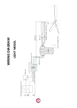
Страница 6: ...5 WIRING DIAGRAM LIGHT MODEL...
Страница 7: ...6 NO LIGHT MODEL...
Страница 16: ......


