11
Parts & Service: 020 8988 7400 / E-mail: [email protected] or [email protected]
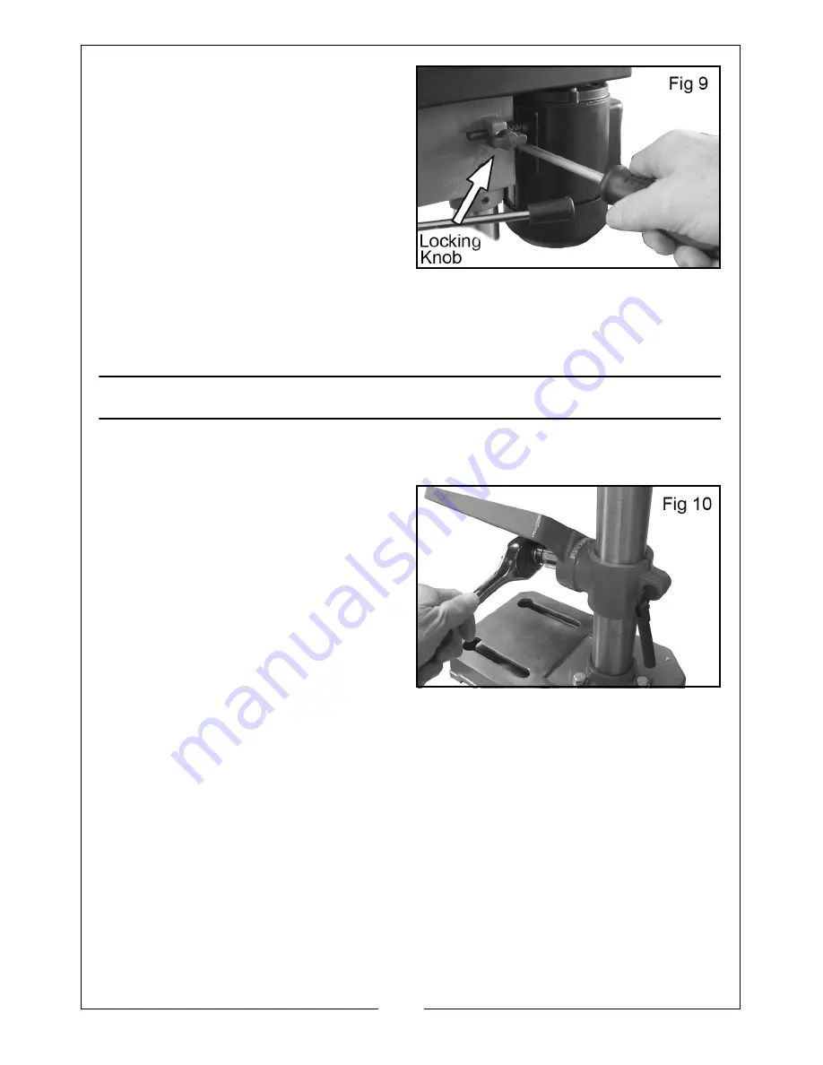
3. Lever the motor/bracket, away
from the head, so that tension is
applied to the belt.
4. Lock the motor in this position
using the locking knob.
NOTE:
If the belt slips whilst drilling,
re-set the belt tension.
IMPORTANT: When closing the cover, check the operation of the safety
switch. It should operate as soon as the cover is unfastened. Undo the
switch actuator fixing screw shown in Fig 8 and adjust if necessary.
SETTINGS AND ADJUSTMENTS
TABLE
The table may be raised, lowered or
swivelled around the column, by
slackening off the table support
locking handle, adjusting
accordingly and re-tightening the
handle.
It may also be tilted by loosening the
bolt beneath the table, tilting the
table to the required position and
re-tightening the bolt shown in Fig 10.
A bevel scale is provided on the table mounting, (measured in degrees), to
assist in setting the required angle. However, for greater accuracy, the use of a
protractor is recommended.
For all normal operations, the table should be set to 0°. To check to ensure the
drill is entirely perpendicular to the table, install a large drill bit in the chuck,
place a set-square on the table, and bring it up to the drill. Adjust the table if
necessary, so that it is perfectly level.


